
Installation Instructions User Manual


6
Publication
1756-IN612B-EN-P - December 2009
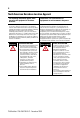
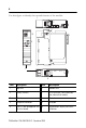
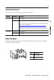
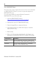
Use this figure to identify the external features of the module.
Item Description Item Description
1 Top view 6 Bottom view
2 Rotary switches 7 RJ45 (Ethernet) cable connectors
(on underside of module)
3 Side view 8 Front view
4 Backplane connector 9 USB port
5 MAC ID label (on opposite side
of circuit board)
10 Alphanumeric display and status
indicators
1
LNK1 LNK2 OK
10/100 BASE T
EtherNet/IP
TM
1 2
3
6
10
9
4
5
7
8
2