Installation Instructions ControlLogix EtherNet/IP Communication Module Catalog Numbers 1756-EN2TR, 1756-EN3TR Topic Page Important User Information 2 Environment and Enclosure 3 Prevent Electrostatic Discharge 5 North American Hazardous Location Approval 4 About the Module 5 Before You Begin 7 Install the Module 11 Status Indicators 19 Specifications 21 Additional Resources 25
Important User Information Solid state equipment has operational characteristics differing from those of electromechanical equipment. Safety Guidelines for the Application, Installation and Maintenance of Solid State Controls, publication (SGI-1.1, available from your local Rockwell Automation sales office or online at http://www.rockwellautomation.com/literature) some important differences between solid state equipment and hard-wired electromechanical devices.
Environment and Enclosure ATTENTION This equipment is intended for use in a Pollution Degree 2 industrial environment, in overvoltage Category II applications (as defined in IEC 60664-1), at altitudes up to 2000 m (6562 ft) without derating. This equipment is considered Group 1, Class A industrial equipment according to IEC/CISPR 11.
North American Hazardous Location Approval The following information applies when operating this equipment in hazardous locations. Informations sur l’utilisation de cet équipement en environnements dangereux. Products marked "CL I, DIV 2, GP A, B, C, D" are suitable for use in Class I Division 2 Groups A, B, C, D, Hazardous Locations and nonhazardous locations only. Each product is supplied with markings on the rating nameplate indicating the hazardous location temperature code.
Prevent Electrostatic Discharge ATTENTION This equipment is sensitive to electrostatic discharge, which can cause internal damage and affect normal operation. Follow these guidelines when you handle this equipment: • • • • • • Touch a grounded object to discharge potential static. Wear an approved grounding wriststrap. Do not touch connectors or pins on component boards. Do not touch circuit components inside the equipment. Use a static-safe workstation, if available.
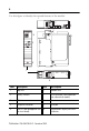
Use this figure to identify the external features of the module.
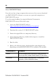
Software Requirements You must have the following versions of software. Module Software Version 1756-EN2TR RSLinx Classic 2.55 or later RSLogix 5000 17.0x (supports revision 2 of module firmware only) If you are using version 17.01 of RSLogix 5000 software, you need to download the add-on-profile. Download it from http://www.rockwellautomation.com/support/controlflash/LogixProfiler.asp or 18 or later (supports revision 2 and later revisions of module firmware) 1756-EN3TR RSLinx Classic 2.
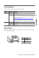
To install these products, refer to these publications. Chassis Type Chassis Installation Instructions Power Supply Power Supply Installation Instructions 1756-A4/B 1756-A7/B 1756-A10/B 1756-A13/B Publication 1756-IN080 1756-PA72/C, 1756-PB72/B, 1756-PA75/B, 1756-PB75/B Publication 1756-IN613 Determine Module Slot Location Install the module in any slot in the ControlLogix chassis. You can install multiple 1756-EN2TR or 1756-EN3TR modules in the same chassis.
Use the Rotary Switches Item 2 1 Description 1 Front of module 2 Top of module 3 Rotary switches 31587 3 The module reads the rotary switches first to determine if they are set to a valid number for the last portion of the IP address. Valid numbers range from 001…254. When the switches are set to a valid number, the module’s IP address is 192.168.1.xxx (where xxx represents the number set on the switches). The module’s subnet mask is 255.255.255.0 and the gateway address is set to 0.0.0.0.
Use a DHCP/BOOTP Server If you do not have a large computer that can act as a boot server, download our DHCP/BOOTP software so you can use a personal computer as a DHCP/BOOTP server. To set the network address by using the Rockwell Automation DHCP/BOOTP server, follow these steps. 1. Access the DHCP/BOOTP utility at http://www.ab.com/networks/ethernet/bootp.html. 2. Download the version 2.3.2 DHCP/BOOTP utility. 3. Extract the zipped files to a temporary directory. 4.
Use RSLinx Classic or RSLogix 5000 Software Follow the procedures outlined in the online help that accompanies this software to set the network address. Install the Module To install the module, follow this procedure. WARNING When you insert or remove the module while backplane power is on, an electrical arc can occur. This could cause an explosion in hazardous location installations. Be sure that power is removed or the area is nonhazardous before proceeding.
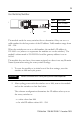
2. Slide the module into the chassis, making sure the module backplane connector properly connects to the chassis backplane and noting that the module is properly installed when it is flush with the power supply or other installed modules. 31589-M Wire the Ethernet Connector Use an RJ45 connector to connect to the EtherNet/IP network. Wire the connector as shown.
Grounding Considerations The grounding and bonding must be of equal potential between all devices in the communication coverage area. Connect the Module to the EtherNet/IP Network Follow this procedure to connect the module to the network. WARNING If you connect or disconnect the communication cable with power applied to this module or any device on the network, an electrical arc can occur. This could cause an explosion in hazardous location installations.
Download the 1756-EN2TR Module Add-on Profile (AOP) [RSLogix 5000 Software Version 17.01 Only] If you are using RSLogix 5000 software, version 17.01, you need to download the AOP. Follow these steps to download the AOP. IMPORTANT The 1756-EN3TR module requires RSLogix 5000 software version 18. 1. Locate the module AOP on http://www.rockwellautomation.com/support/controlflash/LogixProfiler.as. IMPORTANT You need a Rockwell Automation MySupport account to download the AOP.
Use the Module in a Device-level Ring (DLR) Network The module is configured by default to be used in a linear or star topology, or as a ring node in a DLR network. Follow these steps to use the module in a DLR network as a ring supervisor. 1. If you are using the unit as a ring supervisor, follow the procedures outlined in the online help that accompanies RSLinx or RSLogix 5000 software to enable the ring supervisor function with this software.
Use a USB cable to connect your computer to the USB port. The connection lets you download programs to controllers and configure Ethernet modules directly from your computer. ATTENTION The USB cable is not to exceed 3.0 m (9.84 ft) and must not contain hubs. Apply Chassis Power and Check Status Indicators To complete this procedure, follow these steps. 1. Apply chassis power as shown in the figure. 2.
The display then alternates between OK and port link status for both ports. TM 10/100 BASE T LNK1 LNK2 OK LNK1 LNK2 OK Install or Remove the Module Under Power You can install or remove this module while chassis power is applied. WARNING When you insert or remove the module while backplane power is on, an electrical arc can occur. This could cause an explosion in hazardous location installations. Be sure that power is removed or the area is nonhazardous before proceeding.
To remove or replace the module, use this procedure. 1. Push on the upper and lower module tabs to disengage them. 31590-M 2. Slide the module out of chassis. 31591-M IMPORTANT If you want to replace an existing module with an identical one, and you want to resume identical system operation, you must install the new module in the same slot.
Status Indicators If the alphanumeric display and status indicators do not sequence through the expected states, refer to the following troubleshooting tables. The three bi-color (red/green) status indicators on the module provide diagnostic information about the module and its connections to the network. Indicator Status Description LNK1, LNK2 Off No link, or port administratively disabled, or port disabled due to rapid ring faults or partial network fault on active ring supervisor (LNK2).
Indicator Status Description OK Off Module does not have 24V DC power. Verify that there is chassis power and the module is completely inserted into chassis and backplane. Flashing green Module is not configured. Green Module is operating correctly. Flashing red Module detected a recoverable fault. A configuration error may have caused the fault. Red Recycle power to the module. If this does not clear the fault, replace the module.
Specifications Technical Specifications - 1756-EN2TR and 1756-EN3TR Attribute Value Module location Any slot in the ControlLogix chassis Backplane current (mA) at 5.1V DC 1A Backplane current (mA) at 24V DC 3 mA Isolation voltage 30 V (continuous), Basic Insulation Type, Ethernet to system No isolation between USB and system Type tested at 853V AC for 60 s Power consumption, max 5.1 W Power dissipation 5.
Environmental Specifications - 1756-EN2TR and 1756-EN3TR Attribute Value Temperature, operating • IEC 60068-2-1 (Test Ad, Operating Cold) • IEC 60068-2-2 (Test Bd, Operating Dry Heat) • IEC 60068-2-14 (Test Nb, Operating Thermal Shock) 0…60 °C (32…140 °F) Temperature, nonoperating • IEC 60068-2-1 (Test Ab, Unpackaged Nonoperating Cold) • IEC 60068-2-2 (Test Bb, Unpackaged Nonoperating Dry Heat) • IEC 60068-2-14 (Test Na, Unpackaged Nonoperating Thermal Shock) -40…85 °C (-40…185 °F) Relative humidit
Environmental Specifications - 1756-EN2TR and 1756-EN3TR Attribute Value Immunity, radiated RF • IEC 61000-4-3 10V/m with 1 kHz sine-wave 80%AM from 80…2000 MHz 10V/m with 200 Hz 50% Pulse 100%AM at 900 MHz 10V/m with 200 Hz 50% Pulse 100%AM at 1890 MHz 3V/m with 1 kHz sine-wave 80%AM from 2000…2700 MHz Immunity, EFT/B • IEC 61000-4-4 ±3 kV at 5 kHz on Ethernet port Immunity, surge transient • IEC 61000-4-5 ±2 kV line-earth(CM) on Ethernet port Immunity, conducted RF • IEC 61000-4-6 10V rms with
Certifications - 1756-EN2TR and 1756-EN3TR Certification Value When product is marked. See the Product Certification link at http://www.ab.com for Declarations of Conformity, Certificates, and other certification details CE European Union 2004/108/EC EMC Directive, compliant with: • EN 61326-1; Meas./Control/Lab.
Additional Resources These documents contain additional information concerning related Rockwell Automation products. Resource Description EtherNet/IP Modules in Logix5000 Control Systems User Manual, publication ENET-UM001 Provides details about how to configure your module. EtherNet/IP Embedded Switch Technology Application Guide, publication ENET-AP005 Provides information about using products with embedded switch technology to construct networks with linear and ring topologies.
Notes: Publication 1756-IN612B-EN-P - December 2009
Notes: Publication 1756-IN612B-EN-P - December 2009
Rockwell Automation Support Rockwell Automation provides technical information on the Web to assist you in using its products. At http://support.rockwellautomation.com, you can find technical manuals, a knowledge base of FAQs, technical and application notes, sample code and links to software service packs, and a MySupport feature that you can customize to make the best use of these tools.