
User guide

12 ControlLogix-XT EtherNet/IP Bridge Module
Publication
1756-IN635A-EN-P - March 2009
Install the Module
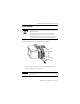
Complete these steps to install the module.
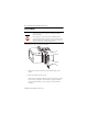
1. Align the circuit board with top and bottom guides in the
cha
ssis.
2. Slide the module into the chassis.
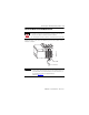
Make sure the module backplane connector properly connects
to the chassis backplane. The module is properly installed
when it is flush with the power supply or other installed
modules.
WARNING
When you insert or remove the module while backplane power is on, an
electrical arc can occur. This could cause an explosion in hazardous
location installations.
Be sure that power is removed or the area is nonhazardous before
proceeding. Repeated electrical arcing causes excessive wear to contacts
on both the module and its mating connector. Worn contacts may create
electrical resistance that can affect module operation.
X
T
LINK
NET
OK
10/100/BASE T
X
T