Installation Instructions ControlLogix-XT EtherNet/IP Bridge Module Catalog Number 1756-EN2TXT Topic Page Important User Information 2 About ControlLogix-XT Systems 8 ControlLogix-XT with Traditional ControlLogix Components Before You Begin 8 9 Determine Module Slot Location 9 Set the Network Address 10 Reset the Module to Initial Settings 11 Install the Module 12 Connect the Module to the EtherNet/IP Network 13 Connect to the Module Via the USB Port 14 Components Required for USB Conne
ControlLogix-XT EtherNet/IP Bridge Module Important User Information Solid state equipment has operational characteristics differing from those of electromechanical equipment. Safety Guidelines for the Application, Installation and Maintenance of Solid State Controls (Publication SGI-1.1 available from your local Rockwell Automation sales office or online at http://literature.rockwellautomation.
ControlLogix-XT EtherNet/IP Bridge Module 3 North American Hazardous Location Approval The following information applies when operating this equipment in hazardous locations. Informations sur l’utilisation de cet équipement en environnements dangereux. Products marked "CL I, DIV 2, GP A, B, C, D" are suitable for use in Class I Division 2 Groups A, B, C, D, Hazardous Locations and nonhazardous locations only.
ControlLogix-XT EtherNet/IP Bridge Module Environment and Enclosure ATTENTION This equipment is intended for use in a Pollution Degree 2 industrial environment, in overvoltage Category II applications (as defined in IEC 60664-1), at altitudes up to 2000 m (6562 ft) without derating. This equipment is considered Group 1, Class A industrial equipment according to IEC/CISPR 11.
ControlLogix-XT EtherNet/IP Bridge Module 5 Preventing Electrostatic Discharge ATTENTION This equipment is sensitive to electrostatic discharge, which can cause internal damage and affect normal operation. Follow these guidelines when you handle this equipment: • Touch a grounded object to discharge potential static. • Wear an approved grounding wriststrap. • Do not touch connectors or pins on component boards. • Do not touch circuit components inside the equipment.
ControlLogix-XT EtherNet/IP Bridge Module European Hazardous Location Approval European Zone 2 Certification (The following applies when the product bears the Ex or EEx Marking) This equipment is intended for use in potentially explosive atmospheres as defined by European Union Directive 94/9/EC and has been found to comply with the Essential Health and Safety Requirements relating to the design and construction of Category 3 equipment intended for use in potentially explosive atmospheres, given in Annex
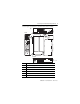
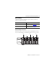
ControlLogix-XT EtherNet/IP Bridge Module 7 Use this figure to identify the external features of the module.
ControlLogix-XT EtherNet/IP Bridge Module About ControlLogix-XT Systems The ControlLogix-XT products include control and communication system components that, when used with FLEX I/O-XT products, provide a complete control system solution that can be used in environments where temperatures range from -20...70 °C (-4...158 °F). When used independently, the ControlLogix-XT system can withstand environments where the temperature ranges from -25...70 °C (-13...158 °F).
ControlLogix-XT EtherNet/IP Bridge Module 9 Before You Begin Complete these tasks by using the resources listed as references before you install your module.
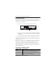
ControlLogix-XT EtherNet/IP Bridge Module Set the Network Address The module ships with the rotary switches set to 999 and BOOTP enabled. You can set the network Internet Protocol (IP) address by using one of these methods: • Use the rotary switches on the top of the module. Rotary Switches 31587 • Use a BOOTP server or Dynamic Host Configuration Protocol (DHCP) server, such as Rockwell Automation’s BootP-DHCP Server tool. • Use Rockwell Automation’s RSLinx or RSLogix 5000 software.
ControlLogix-XT EtherNet/IP Bridge Module 11 Reset the Module to Initial Settings To reset the module to its initial out-of-the-box settings, reset the switches to 888 and cycle power. IMPORTANT Do not use the 888 switch setting during normal module operation. After cycling power with the switches set to 888, remove the module and set the switches to their final value.
ControlLogix-XT EtherNet/IP Bridge Module Install the Module WARNING When you insert or remove the module while backplane power is on, an electrical arc can occur. This could cause an explosion in hazardous location installations. Be sure that power is removed or the area is nonhazardous before proceeding. Repeated electrical arcing causes excessive wear to contacts on both the module and its mating connector. Worn contacts may create electrical resistance that can affect module operation.
ControlLogix-XT EtherNet/IP Bridge Module 13 Connect the Module to the EtherNet/IP Network WARNING If you connect or disconnect the communication cable with power applied to this module or any device on the network, an electrical arc can occur. This could cause an explosion in hazardous location installations. Be sure that power is removed or the area is nonhazardous before proceeding. Attach the RJ45 connector to the Ethernet port on the bottom of the module as shown.
ControlLogix-XT EtherNet/IP Bridge Module Connect to the Module Via the USB Port WARNING The USB port is intended for only for temporary local programming purposes and is not intended for permanent connection. If you connect or disconnect the USB cable with power applied to this module or any device on the USB network, an electrical arc can occur. This could cause an explosion in hazardous location installations. Be sure that power is removed or the area is nonhazardous before proceeding. A Samtec Inc.
ControlLogix-XT EtherNet/IP Bridge Module 15 Apply Chassis Power Apply power to the ControlLogix-XT power supply to supply power to the EtherNet/IP module installed in the chassis. Check Power Supply and Module Status After power is applied, check the: • power supply status indicator. • module status indicators. • module alphanumeric display. These indicators indicate if the module is operating properly.
ControlLogix-XT EtherNet/IP Bridge Module Alphanumeric Display Start-up Indications Upon installation and powerup, the alphanumeric display of the module cycles through these states: 1. 2. 3. 4. TEST PASS OK REV X.X (X.X is the module’s current firmware revision). Once that cycle is complete, the display alternates between OK and the module’s EtherNet/IP address. Install the EDS File The EDS file can be uploaded directly from the module.
ControlLogix-XT EtherNet/IP Bridge Module 17 Remove the Module WARNING When you insert or remove the module while backplane power is on, an electrical arc can occur. This could cause an explosion in hazardous location installations. Be sure that power is removed or the area is nonhazardous before proceeding. Repeated electrical arcing causes excessive wear to contacts on both the module and its mating connector. Worn contacts may create electrical resistance that can affect module operation.
ControlLogix-XT EtherNet/IP Bridge Module Status Indicators Use these tables to interpret the status indicators. NET Status Indicator State Description Off The module is not powered. Verify that there is chassis power and that the module is completely inserted into the chassis and backplane. The module does not have a valid IP address. Make sure the module has been configured with a valid IP address. Flashing green The module has an IP address, but has no established connections.
ControlLogix-XT EtherNet/IP Bridge Module 19 OK Status Indicator State Description Off Verify that the module has 24V DC chassis power and that the module is completely inserted into chassis and backplane. Flashing green The module is not configured. Green The module is operating correctly. Flashing red The module detected a recoverable fault. A configuration error may have caused the fault. Check the module configuration. If necessary, reconfigure the module.
ControlLogix-XT EtherNet/IP Bridge Module General Specifications - 1756-EN2TXT Attribute Value Module location Any slot in the ControlLogix-XT chassis Backplane current (mA) at 5V.1V DC 1A Backplane current (mA) at 24V DC 3 mA Enclosure Type Rating None (open-style) Isolation voltage 30 V (continuous), Basic Insulation Type No isolation between USB and system. Type tested at 853V AC for 60 s, Ethernet to system. Power consumption 17.1 BTU/hr Power dissipation 5.
ControlLogix-XT EtherNet/IP Bridge Module 21 Environmental Specifications - 1756-EN2TXT Attribute Value Temperature, operating -25…70 °C (-13…158 °F) IEC 60068-2-1 (Test Ad, Operating Cold), IEC 60068-2-2 (Test Bd, Operating Dry Heat), IEC 60068-2-14 (Test Nb, Operating Thermal Shock) Temperature, nonoperating -40…85 °C (-40…185 °F) IEC 60068-2-1 (Test Ab, Unpackaged Nonoperating Cold), IEC 60068-2-2 (Test Bb, Unpackaged Nonoperating Dry Heat), IEC 60068-2-14 (Test Na, Unpackaged Nonoperating Thermal
ControlLogix-XT EtherNet/IP Bridge Module Attribute Value EFT/B immunity ±2 kV at 5 kHz on Ethernet port IEC 61000-4-4 Surge transient immunity IEC 61000-4-5 Conducted RF immunity IEC 61000-4-6 Publication 1756-IN635A-EN-P - March 2009 ±2 kV line-earth (CM) on Ethernet port 10V rms with 1 kHz sine-wave 80% AM from 150 kHz…80 MHz
ControlLogix-XT EtherNet/IP Bridge Module 23 Certifications - 1756-EN2TXT Certification(1) (2) Value c-UL-us UL Listed Industrial Control Equipment, certified for US and Canada. See UL File E65584. UL Listed for Class I, Division 2 Group A,B,C,D Hazardous Locations, certified for U.S. and Canada. See UL File E194810. CE European Union 2004/108/EC EMC Directive, compliant with: • EN 61326-1; Meas./Control/Lab.
Additional Resources Resource Description Industrial Automation Wiring and Grounding Guidelines, publication 1770-4.