User Manual EtherNet/IP Secure Communication Catalog Number 1756-EN2TSC
Important User Information Read this document and the documents listed in the additional resources section about installation, configuration, and operation of this equipment before you install, configure, operate, or maintain this product. Users are required to familiarize themselves with installation and wiring instructions in addition to requirements of all applicable codes, laws, and standards.
Summary of Changes This manual contains new and updated information. Changes throughout this revision are marked by change bars, as shown to the right of this paragraph. New and Updated Information This table contains the changes made to this revision.
Summary of Changes Notes: 4 Rockwell Automation Publication ENET-UM003B-EN-P - September 2013
Table of Contents Preface Additional Resources . . . . . . . . . . . . . . . . . . . . . . . . . . . . . . . . . . . . . . . . . . . . . . . 7 Chapter 1 Secure Communication Architecture Considerations . . . . . . . . . . . . . . . . . . . . . . . . . . . . . . . . . . . . . . . . . . . . . . . Local Chassis Security . . . . . . . . . . . . . . . . . . . . . . . . . . . . . . . . . . . . . . . . Network Access Security. . . . . . . . . . . . . . . . . . . . . . . . . . . . . . . . . . . . . . . . . .
Table of Contents Diagnostics Diagnostic Web Pages . . . . . . . . . . . . . . . . . . . . . . . . . . . . . . . . . . . . . . . . . . . . Secure Tunnel Diagnostics Web Page . . . . . . . . . . . . . . . . . . . . . . . . . . . . . . Status Indicators . . . . . . . . . . . . . . . . . . . . . . . . . . . . . . . . . . . . . . . . . . . . . . . . . Link (LINK) Status Indicator . . . . . . . . . . . . . . . . . . . . . . . . . . . . . . . . . Network (NET) Status Indicator . . . . . . . . . . . . . . . . .
Preface The 1756-EN2TSC is a security-enhanced version of the 1756-EN2T EtherNet/IP communication module. This module is designed for applications that need to limit network access to a control system from within the plant network. This module is not intended to connect any devices in the local 1756 backplane to devices outside of the plant firewall. Additional Resources These documents contain additional information concerning related products from Rockwell Automation.
Preface Notes: 8 Rockwell Automation Publication ENET-UM003B-EN-P - September 2013
Chapter 1 Secure Communication Architecture Topic Page Network Access Security 12 Performance 14 Many control systems currently use 1756-EN2T and 1756-ENBT modules to connect ControlLogix® systems to plant-level systems. A 1756-EN2TSC module offers the same connectivity, as well as additional security options to protect access to resources on the local backplane from the plant network Use the 1756-EN2TSC module to establish secure tunnels with peer modules, Windows 7 clients, and VPN appliances.
Chapter 1 Secure Communication Architecture The 1756-EN2TSC module provides a level of protection against unauthorized network access, either malicious or accidental, to a ControlLogix controller via an EtherNet/IP connection. The 1756-EN2TSC module uses the IPsec protocol suite to provide a secure communication tunnel. The 1756-EN2TSC module is intended for use behind an existing firewall/DMZ that protects the plant network from outside access.
Secure Communication Architecture Chapter 1 Local Chassis Security You can use the 1756-EN2TSC module with the following features to prevent unauthorized access to a controller in the local chassis. • The trusted slot feature (in the controller properties) designates slots in the local chassis as trusted. When the trusted slot feature is enabled, the controller denies communication through paths that are not trusted.
Chapter 1 Secure Communication Architecture The trusted slot and serial number lock features are for applications that have concern with physical access to and tampering with the controller. IMPORTANT Network Access Security Use caution with these features and make sure you have the controller project backed up in a secure location. If the module becomes disabled for any reason, you have to download to the controller to recover.
Secure Communication Architecture Chapter 1 As part of establishing the secure tunnel, both endpoints must authenticate with each other and exchange information to ensure secure data transfer.
Chapter 1 Secure Communication Architecture Performance The basic communication capability of the module is the same as the 1756-EN2T module. • The module supports the same number of TCP and CIP connections as the 1756-EN2T module (256 CIP connections and 128 TCP/IP connections). • The module supports configuration of IPsec associations with as many as 8 IP addresses (devices); only 1 of which can be a Cisco ASA connection. • The module supports CIP Sync communication.
Chapter 2 Get Started Topic Page Initial Powerup 16 Configuration Overview 18 Assign Network Settings 19 Configuration Overview 18 Create User Accounts 21 Generate HTTPS Certificate 23 Backup / Restore 25 This chapter describes the initial configuration settings required for the module. After setting up the module, see the next chapters for security configuration examples.
Chapter 2 Get Started Configure all security parameters via the web server. In the Address field of your web browser, enter the IP address that displays on the front of the module. Specify the IP address of the web server module in the Address window of your web browser. This is the module’s Home page. 'The 1756-EN2TSC module has an embedded HTTPS server that it uses to provide secure web communication. An HTTPS server uses a certificate so that the client can verify server authenticity.
Get Started Chapter 2 2. After the web browser connects to the server, a warning message is shown about the certificate not being signed by a trusted authority. Accept this message and continue to the web page. IMPORTANT In general, do not accept the certificate not being signed by a trusted authority. But in the case of initial powerup, the module has a self-signed certificate, so continue to the website even though the message says this option is not recommended.
Chapter 2 Get Started Default Credentials Default credentials are case sensitive and are as follows: • User name: Administrator • Password: admin You are prompted to change the password on the Administrator account. Enter the new password and click Change. The browser prompts you to authenticate again. Use the Administrator user name and new password. Configuration Overview 18 The left pane of the web browser is a navigation tree to configure and maintain the module.
Get Started Chapter 2 See the next chapters in this manual for different security configurations. Assign Network Settings By default, the module is BOOTP enabled. IMPORTANT Do not simply configure the initial address assigned to the module as a static IP address. Contact your network administrator for an appropriate static IP address. Choose one of the following methods to assign an IP address.
Chapter 2 20 Get Started In This Field Specify Ethernet Interface Configuration The network configuration scheme: • Dynamic BOOTP (default) • Dynamic DHCP • Static IP Address IP address for the module: If you want to specify a static IP address for the module, you must also choose Static for the Ethernet Interface Configuration field. Subnet Mask Subnet mask for the module. Default Gateway Gateway address for the module.
Get Started Create User Accounts Chapter 2 You can define user accounts for the web interface to the module. These accounts are typically for administrators or others who need to access the module’s diagnostic information. Assign user accounts with access levels to manage who has access to change configuration or to view module information. Define each user as a member of the Users group or the Administrators group. Members of the Administrators group have all access rights to the module.
Chapter 2 Get Started From this form, you can change the following: • Password • Group membership • Status (enabled or disabled) You cannot change the user name. Edit Access Limits To add or remove access rights for a user to web pages, access Administrative Settings > User Management > Edit Access Limits. Default access limits allow members of the Users group to access status and diagnostic pages and diagnostics, but limit configuration pages to members of the Administrators group.
Get Started Chapter 2 Some web pages use both .asp, form, and URL elements. In such cases, each element is represented by a separate access limit. For example, the ‘Edit Access Limits’ web page is composed of the following: • editlimits.asp to generate a list of access limits • /rokform/AddAccessLimits to add or update an existing limit • /rokform/DeleteAccessLimit to delete an existing limit IMPORTANT Generate HTTPS Certificate Limiting access to the .asp file is not enough to limit its functionality.
Chapter 2 Get Started Certificates On initial powerup, the subject common name (CN) of the self-generated certificate is set to Rockwell Automation. When you generate a new certificate, the CN is changed to the IP address of the module and the new certificate is applied at the next restart of the module.
Get Started Chapter 2 To back up module configuration, choose Administrative Settings > Backup / Restore > Backup. Backup / Restore Choose which items to include in the back-up configuration.
Chapter 2 Get Started 1. Specify the back-up file to use. 2. If the back-up file is password protected, enter the password when prompted. 3. When prompted that the restore overwrites the module, click OK. When the restore is complete, the module displays a status message. The module is now configured so that the 888 Factory Reset feature is enabled in case you need to reset the module to factory settings.
Chapter 3 Configure a Secure Connection to a Microsoft Windows Client Topic Page Configure a Mobile Client 29 Configure a Connection to a Microsoft Windows Client 34 Open the VPN Connection to the 1756-EN2TSC Module 42 Communicate to the Module via an RSLinx Driver 43 In this scenario a Microsoft Windows 7 client establishes an IPsec association with the 1756-EN2TSC module.
Chapter 3 Configure a Secure Connection to a Microsoft Windows Client To configure this secure connection, do the following. 1. Configure the 1756-EN2TSC module to support a connection to a mobile client. 2. Configure a connection to the Microsoft Windows client. 3. Open the connection. L2TP Connections The 1756-EN2TSC module uses Layer 2 Tunneling Protocol (L2TP) connections for Windows clients. Communication occurs within an L2TP tunnel (after VPN is already running).
Configure a Secure Connection to a Microsoft Windows Client Chapter 3 The Microsoft IPSec client uses classful network-addressing architecture. • The traffic from a Windows client is directed to a specific VPN based on the class of the IP address set in the L2TP configuration. • Class C addresses (192.168.0.0 through 192.168.255.255) provide the fewest addresses and supports as many as 256 non-overlapping subnets. Class C addresses also ensure that no IP address is masked by the active VPN connection.
Chapter 3 Configure a Secure Connection to a Microsoft Windows Client 1. Log in to the 1756-EN2TSC module and choose Administrative Settings > Secure Tunnel Configuration> IPsec Configuration. 2. On the right side of the screen, check Enable to enable IPsec connections. 3. In the Add a Security Association (SA) area, do the following. a. Enter the Identifier as a text description of the connection. b. Choose the Windows Client profile. c. Enter the Remote IP address.
Configure a Secure Connection to a Microsoft Windows Client Chapter 3 4. Click Add. 5. Click Apply Changes. 6. Verify IPsec connections are enabled. 7. Choose Administrative Settings > Secure Tunnel Configuration> Mobile Clients.
Chapter 3 Configure a Secure Connection to a Microsoft Windows Client 8. Make the following configuration selections. a. Check Enable Mobile Clients. b. Enter the pre-shared key and confirm the pre-shared key. If there are already characters in the pre-shared key field, delete those characters and re-enter the same pre-shared key you entered on the IPsec Configuration tab. c. Choose an encryption algorithm. 9. Click Apply Changes. 10.
Configure a Secure Connection to a Microsoft Windows Client Chapter 3 11. If needed, change the range of available client IP addresses The IP addresses on this screen are the virtual IP addresses for the L2TP server (in the 1756-EN2TSC module) and the pool of virtual IP addresses (for Windows clients). Once the secure tunnel is established, use the L2TP server IP address to identify the 1756-EN2TSC module. The Windows client will use an IP address from the L2TP pool. 12. Click Apply Changes. 13.
Chapter 3 Configure a Secure Connection to a Microsoft Windows Client 15. Click Add. Configure a Connection to a Microsoft Windows Client An IPsec client is required to make a secure connection to the module. Without an active IPsec association, the module drops packets, which appear as message timeouts. The IPsec client comes pre-installed in the Windows 7 operating system. To configure a Microsoft Windows client, do the following. 1. From the Control Panel, open the Network and Sharing Center. 2.
Configure a Secure Connection to a Microsoft Windows Client Chapter 3 4. Select No, create a new connection and click Next. You do not see this screen if there are no connections set. 5. Choose Connect using a virtual private network (VPN) connection through the internet. 6. If prompted, choose I’ll set up an Internet connection later.
Chapter 3 Configure a Secure Connection to a Microsoft Windows Client 7. Enter the physical IP address of the 1756-EN2TSC module and a name for the connection. 8. Select Don’t connect now; just set it up so I can connect later and click Next. 9. Enter the appropriate user name and password. The user name and password must have already been configured as an L2TP user on the 1756-EN2TSC module. See the L2TP Edit Users tab as part of configuring the 1756-EN2TSC module (page 33). 10.
Configure a Secure Connection to a Microsoft Windows Client Chapter 3 12. Once the connection is created, click Close. 13. Click the network icon in the right, bottom corner of the Windows taskbar. 14. Select the created connection, right-click, and choose Properties.
Chapter 3 Configure a Secure Connection to a Microsoft Windows Client 15. On the Options tab, do the following. a. Check Display progress while connecting. b. Check Prompt for name and password, certificate, etc. c. Clear Include Windows logon domain. d. Accept the defaults for PPP settings.
Configure a Secure Connection to a Microsoft Windows Client Chapter 3 16. On the Security tab, do the following. a. Choose Layer 2 Tunneling Protocol with IPsec (L2TP/IPsec) as the type of VPN. b. Choose Optional encryption (connect even if no encryption) as the type of data encryption. IMPORTANT c. d. e. f. This setting means that the L2TP configuration does not enforce encryption, but there still is IPsec encryption. Click Allow these protocols. Check Unencrypted password (PAP).
Chapter 3 Configure a Secure Connection to a Microsoft Windows Client 18. On the Networking tab, check Internet Protocol Version 4 (TCP/IPv4). 19. On the Networking tab, click Properties and then click Advanced. By default all the traffic is forwarded through the established VPN tunnel. To have both the VPN tunnel to the 1756-EN2TSC module and preserve access to the local network (such as Internet or corporate mail server), do the following. a. Clear the Use default gateway on remote network checkbox. b.
Configure a Secure Connection to a Microsoft Windows Client Chapter 3 Interface Metric The interface metric specifies an integer cost metric (1…9999) for the route. This metric is used when choosing among multiple routes in the routing table that most closely match the destination address of a packet being forwarded. • Use the ipconfig command to identify the IP address of the default gateway. • Use the route print command to identify the metric of the default gateway.
Chapter 3 Configure a Secure Connection to a Microsoft Windows Client Open the VPN Connection to the 1756-EN2TSC Module Once the Windows client and 1756-EN2TSC module are configured, you must establish the VPN connection. 1. From the Windows notification area, select the network icon. 2. Right-click the EN2TSC VPN Connection and click Connect. 3. Log on with your 1756-EN2TSC user name and password. It can take 30 seconds or more to connect.
Configure a Secure Connection to a Microsoft Windows Client Communicate to the Module via an RSLinx Driver Chapter 3 If you communicate to the module through an RSLinx driver, you must use an L2TP connection and the Ethernet devices (AB_ETH-1) driver. Once the secure tunnel exists to the 1756-EN2TSC module, RSLinx software uses the L2TP server IP addresses to communicate with the controller through the 1756-EN2TSC module.
Chapter 3 Configure a Secure Connection to a Microsoft Windows Client If you connect to the 1756-EN2TSC module without knowing the L2TP server IP address, you can find that after the connection is established. 1. Click the network icon in the right, bottom of the Windows taskbar. 2. Choose Status. 3. Click the Details tab. RSLinx software uses the L2TP server IP address to communicate with the 1756-EN2TSC module inside the secure tunnel.
Chapter 4 Configure Secure Communication Between Two 1756-EN2TSC Modules Topic Page Configure the First (Local) Module 47 Configure the Second (Remote) Module 48 Test the Connection 49 Edit the Security Association 49 In this scenario an IPsec association is established between two 1756-EN2TSC modules (peer-to-peer). In this case, there are remote and local IP networks serviced by a VPN tunnel. There is one IP address at either end of the IPsec association.
Chapter 4 Configure Secure Communication Between Two 1756-EN2TSC Modules To create a security association with another module, each module must be configured with the pre-shared key of the other module.
Configure Secure Communication Between Two 1756-EN2TSC Modules Configure the First (Local) Module Chapter 4 1. Choose Administrative Settings > Secure Tunnel Configuration > IPsec Configuration and make sure that Enable IPsec is enabled. 2. To create a new secure association, do the following. a. Enter the Identifier as a text description of the connection. b. Choose the Peer to Peer as the Profile. c. Enter the IP address of the second (remote) module. d.
Chapter 4 Configure Secure Communication Between Two 1756-EN2TSC Modules Configure the Second (Remote) Module 1. Choose Administrative Settings > Secure Tunnel Configuration > IPsec Configuration and make sure that Enable IPsec is enabled. 2. To create a new secure association, do the following. a. Enter the Identifier as a text description of the connection. b. Choose the Peer to Peer as the Profile. c. Enter the IP address of the first (local) module. d.
Configure Secure Communication Between Two 1756-EN2TSC Modules Chapter 4 Test the Connection When the security association is added on both sides of connection, the modules take a few seconds to establish the IPsec tunnel between the modules. To verify that the connection is established, access Diagnostics > Advanced Diagnostics > Secure Tunnel > IPsec Security Associations.
Chapter 4 Configure Secure Communication Between Two 1756-EN2TSC Modules Notes: 50 Rockwell Automation Publication ENET-UM003B-EN-P - September 2013
Chapter 5 Configure a Secure Connection to a VPN Appliance Topic Page Configure the Module to Connect to a VPN Appliance 53 Edit the Security Association 54 In this scenario, a VPN appliance (such as a firewall) establishes the IPsec association with the 1756-EN2TSC module. Client workstations or other modules then establish IPsec associations with the VPN appliance. The VPN appliance then routes packets between the IPsec associations.
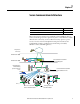
Chapter 5 Configure a Secure Connection to a VPN Appliance Enterprise Zone Levels 4 and 5 Demilitarized Zone (DMZ) Secure Tunnel to VPN Appliance Demilitarized Zone (DMZ) Manufacturing Zone Site Manufacturing Operations and Control Level 3 Level 0…2 ControlLogix Chassis with 1756-EN2TSC Module An appliance like the Cisco ASA supports multiple methods for authentication, multiple encryption algorithms, and multiple types of VPN technology (such as SSL VPN.
Configure a Secure Connection to a VPN Appliance Configure the Module to Connect to a VPN Appliance Chapter 5 1. Choose Administrative Settings > Secure Tunnel Configuration > IPsec Configuration and make sure that Enable IPsec is enabled. 2. To create a new secure association, do the following. a. Enter the Identifier as a text description of the connection. b. Choose the VPN Appliance as the Profile. c. Enter the IP address of the VPN appliance. d.
Chapter 5 Configure a Secure Connection to a VPN Appliance 4. Click Apply Changes. Edit the Security Association 54 If you want to edit the settings for the association you just created, click the Edit button next to the association in the list.
Configure a Secure Connection to a VPN Appliance Chapter 5 Set the key life time (10 min…8 hr) and key life data (1000…10000000 KB) values to the same value as on the VPN appliance. If these values differ, there can be issues with rekeying, even though the initial connection is successful. You must specify a value for key life time. If key life data is not used, set the value to 0.
Chapter 5 Configure a Secure Connection to a VPN Appliance Notes: 56 Rockwell Automation Publication ENET-UM003B-EN-P - September 2013
Chapter 6 Diagnostics Diagnostic Web Pages Topic Page Diagnostic Web Pages 57 Secure Tunnel Diagnostics Web Page 58 Status Indicators 59 The 1756-EN2TSC module supports the same diagnostic web pages as the 1756-EN2T modules, including these pages.
Chapter 6 Diagnostics Secure Tunnel Diagnostics Web Page 58 For specific diagnostics regarding secure connections, choose Diagnostics > Advanced Diagnostics > Secure Tunnel.
Diagnostics Chapter 6 The 1756-EN2TSC module uses the same status indicators as the 1756-EN2T module: • Module Status Display • Link Status Indicator (LINK) • Network Status Indicator (NET) • OK Status Indicator (OK) Status Indicators VPN Module Status Display Link Status Indicator (LINK) OK Status Indicator Network Status Indicator (NET) Link (LINK) Status Indicator Status Description Off One of these conditions exists: • The module is not powered. – Verify there is chassis power.
Chapter 6 Diagnostics Network (NET) Status Indicator Status Description Off One of these conditions exists: • The module is not powered. – Verify there is chassis power. – Verify that the module is completely inserted into the chassis and backplane. – Make sure the module has been configured. • The module is powered but does not have an IP address. Assign an IP address to the module.
Index A access limits 22 additional resources 7, 15 architecture Microsoft Windows client to module 27 module to module 45 secure communication 9 VPN appliance to module 51 IPsec capability 12 modes 13 L L2TP RSLinx driver 43 local chassis security 11 B backup 25 BOOTP 19 browers 10 C certificate generate 23 powerup 16 configure access limits 22 client via RSLinx driver 43 interface metric 41 Microsoft Windows client 34 mobile client 29 module to module 47, 48 network settings 19 overview 18 powerup 16
Index T test connection 49 traffic filtering 14 trusted slot 11 U user account 21 V VPM appliance to module scenario 51 W web pages diagnostics 57 network settings 19 62 Rockwell Automation Publication ENET-UM003B-EN-P - September 2013
Rockwell Automation Support Rockwell Automation provides technical information on the Web to assist you in using its products. At http://www.rockwellautomation.com/support you can find technical and application notes, sample code, and links to software service packs. You can also visit our Support Center at https://rockwellautomation.custhelp.com/ for software updates, support chats and forums, technical information, FAQs, and to sign up for product notification updates.