Installation Instructions ControlLogix DeviceNet Scanner Module Catalog Numbers 1756-DNB, Series C and D Topic Page Important User Information 2 Preventing Electrostatic Discharge 3 European Hazardous Location Approval - European Zone 2 Certification 4 Environment and Enclosure 5 North American Hazardous Location Approval 6 About this Publication 6 About the Module 7 Before You Begin 7 Determine Module Slot Location 8 Change Module Settings 9 Install the Module in the Chassis 16 Con
ControlLogix DeviceNet Scanner Module Important User Information Solid state equipment has operational characteristics differing from those of electromechanical equipment. Safety Guidelines for the Application, Installation and Maintenance of Solid State Controls Publication SGI-1.1 available from your local Rockwell Automation sales office or online at http://literature.rockwellautomation.com) describes some important differences between solid state equipment and hard-wired electromechanical devices.
ControlLogix DeviceNet Scanner Module 3 Preventing Electrostatic Discharge ATTENTION This equipment is sensitive to electrostatic discharge, which can cause internal damage and affect normal operation. Follow these guidelines when you handle this equipment: • Touch a grounded object to discharge potential static. • Wear an approved grounding wriststrap. • Do not touch connectors or pins on component boards. • Do not touch circuit components inside the equipment.
ControlLogix DeviceNet Scanner Module European Hazardous Location Approval - European Zone 2 Certification The following applies when the product bears the EEx Marking). This equipment is intended for use in potentially explosive atmospheres as defined by European Union Directive 94/9/EC.
ControlLogix DeviceNet Scanner Module 5 Environment and Enclosure ATTENTION This equipment is intended for use in a Pollution Degree 2 industrial environment, in overvoltage Category II applications (as defined in IEC publication 60664-1), at altitudes up to 2000 m (6562 ft) without derating. This equipment is considered Group 1, Class A industrial equipment according to IEC/CISPR Publication 11.
ControlLogix DeviceNet Scanner Module North American Hazardous Location Approval The following information applies when operating this equipment in hazardous locations. Informations sur l’utilisation de cet équipement en environnements dangereux. Products marked "CL I, DIV 2, GP A, B, C, D" are suitable for use in Class I Division 2 Groups A, B, C, D, Hazardous Locations and nonhazardous locations only.
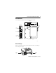
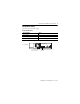
ControlLogix DeviceNet Scanner Module 7 About the Module Use this figure to identify the external features of the module. Top View Front View Backplane Connector Front Panel USB Port DeviceNet Port Side View 31713-M Before You Begin Before you install the module, you must install and connect a ControlLogix chassis and power supply.
ControlLogix DeviceNet Scanner Module To install these products, refer to these publications. Publication References Chassis Type Chassis Installation Instructions Power Supply Power Supply Installation Instructions Series B: 1756-A4, 1756-A7, 1756-A10, 1756-A13 Pub. No. 1756-IN080 1756-PA72/B Pub. No. 1756-IN078 1756-PB72/B 1756-PA75/A Pub. No. 1756-IN596 1756-PB75/A Determine Module Slot Location Install the module in any slot in the ControlLogix chassis.
ControlLogix DeviceNet Scanner Module 9 Change Module Settings The module ships with these settings.
ControlLogix DeviceNet Scanner Module Set the Communication Rate The 1756-DNB scanner module supports the following DeviceNet network communication rates: • 125 Kbps • 250 Kbps • 500 Kbps The factory default setting is 125 Kbps. ATTENTION Do not change the communication rate on an active network. Unpredictable operation may result. In addition, the new communication rate does not take effect until you cycle power to the 1756-DNB scanner module.
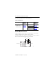
ControlLogix DeviceNet Scanner Module 11 Communication Rate Rotary Switch Top of Module Front of Module Communication (Data) Rate Rotary Switch 31587 Switch Settings and Communication Rate Switch Setting Communication Rate 0 125 Kbps 1 250 Kbps 2 500 Kbps 8 When all three switches are set to 8, this resets the 1756-DNB scanner module to factory default settings. Do not use for normal operation. All other values Select the communication rate with RSNetWorx for DeviceNet software.
ControlLogix DeviceNet Scanner Module Set the Rotary Switch Use the communication (data) rate rotary switch to change the communication rate. TIP For ease of access, remove the module from the chassis before proceeding. 1. If the module is removed from the chassis, be sure that power is removed or the area is nonhazardous before proceeding. 2. Move the rotary switch to the desired position. 3. If necessary, reinstall the module into the chassis.
ControlLogix DeviceNet Scanner Module 13 5. In the Data Rate field, select the communication (data) rate. 6. Click Apply. 7. Cycle power to the 1756-DNB scanner module. Set the Node Address The 1756-DNB scanner module supports DeviceNet node addresses 00...63. The factory default setting is node address 63. Change the node address by setting the rotary switches or commissioning the 1756-DNB scanner module in RSNetWorx for DeviceNet software.
ControlLogix DeviceNet Scanner Module Set the Rotary Switches Use the node address rotary switches to change the DeviceNet node address for the 1756-DNB scanner module. TIP For ease of access, remove the module from the chassis before proceeding. 1. If the module is removed from the chassis, be sure that power is removed or the area is nonhazardous before proceeding. 2. Move the rotary switches to the desired position. 3. If necessary, reinstall the module into the chassis.
ControlLogix DeviceNet Scanner Module 15 Restore the Factory Default Settings The out-of-box reset will clear the scanlist (including ADR configuration recovery files) and return all software setting attributes to their default values. Follow this procedure to restore the factory default communication rate and node address. 1. Set the switches to 888. IMPORTANT Do not use the 888 switch setting during normal module operation. 2. Restore power to the module.
ControlLogix DeviceNet Scanner Module Install the Module in the Chassis WARNING When you insert or remove the module while backplane power is on, an electrical arc can occur. This could cause an explosion in hazardous location installations. Be sure that power is removed or the area is nonhazardous before proceeding. Repeated electrical arcing causes excessive wear to contacts on both the module and its mating connector. Worn contacts may create electrical resistance that can affect module operation.
ControlLogix DeviceNet Scanner Module 17 Wire the DeviceNet Connector Use an open-style 5- or 10-position linear plug to connect to the DeviceNet network. An open-style 10-position linear plug is provided with your module. IMPORTANT For detailed DeviceNet connection information, see the DeviceNet Media Design and Installation Guide, publication DNET-UM072. Also see the Industrial Automation Wiring and Grounding Guidelines, publication 1770-2.1. Wire the connector according to the following illustrations.
ControlLogix DeviceNet Scanner Module Connect the Module to the DeviceNet Network WARNING If you connect or disconnect the DeviceNet connector with power applied to this module or any device on the network, an electrical arc can occur. This could cause an explosion in hazardous location installations. Be sure that power is removed or the area is nonhazardous before proceeding. Attach the connector to the module’s DeviceNet port as shown below. Tighten the screws on the connector as needed.
ControlLogix DeviceNet Scanner Module 19 Connect to the Module Via the USB Port WARNING The USB port is intended for temporary local programming purposes only and is not intended for permanent connection. If you connect or disconnect the USB cable with power applied to this module or any device on the USB network, an electrical arc can occur. This could cause an explosion in hazardous location installations. Be sure that power is removed or the area is nonhazardous before proceeding. A Samtec Inc.
ControlLogix DeviceNet Scanner Module Set Up the USB Driver IMPORTANT The 1756-DNB scanner module must be powered up before proceeding with the USB driver setup. To connect your 1756-DNB scanner module via a USB port, you need to first set up a USB driver. To set up a USB driver, perform this procedure. 1. Connect your 1756-DNB scanner module via a USB port. The Found New Hardware Wizard dialog appears. 2. Check Install the software automatically (Recommended). 3. Click Next.
ControlLogix DeviceNet Scanner Module 21 These dialogs appear consecutively. 4. Click Finish to set up your USB driver.
ControlLogix DeviceNet Scanner Module 5. In RSLinx software, from the Communications pull-down menu, choose RSWho to view your module. The RSLinx Workstation organizer appears. Virtual Chassis Driver USB Port Driver Your module appears under two different drivers, a virtual chassis and the USB port. You can use either driver to browse through your 1756-DNB scanner module. Flash Upgrade Firmware through a USB Port You may flash upgrade the firmware for one module through a USB port.
ControlLogix DeviceNet Scanner Module 23 IMPORTANT Do not simultaneously flash upgrade the firmware for more than one module through a USB port. If you do, one or more of the flash updates may fail in the middle of the download.
ControlLogix DeviceNet Scanner Module Check Power Supply and Module Status Check the status indicators and alphanumeric display to determine if the power supply and module are operating properly. See see Monitor and Troubleshoot Devices in the Module Scan List on page 27. I/O MOD/NET Alphanumeric Display OK indicator is red during self-test, then green. Power Supply indicator is green. When you apply chassis power, the alphanumeric display cycles through the following information: DeviceNetTM 1.
ControlLogix DeviceNet Scanner Module 25 Install or Remove the Module Under Power You can install or remove this module while chassis power is applied. WARNING When you insert or remove the module while backplane power is on, an electrical arc can occur. This could cause an explosion in hazardous location installations. Be sure that power is removed or the area is nonhazardous before proceeding. Repeated electrical arcing causes excessive wear to contacts on both the module and its mating connector.
ControlLogix DeviceNet Scanner Module Remove or Replace the Module 1 Push on upper and lower module tabs to disengage them. 31719-M 2 31720-M Slide module out of chassis. IMPORTANT If you want to replace an existing module with an identical one, and you want to resume identical system operation, you must install the new module in the same slot.
ControlLogix DeviceNet Scanner Module 27 Configure the Scan List Use RSNetWorx for DeviceNet software to configure the scan list for the 1756-DNB scanner module. Refer to DeviceNet Modules in Logix5000 Control Systems, publication DNET-UM004. Monitor and Troubleshoot Devices in the Module Scan List Use the alphanumeric display and the status indicators on the 1756-DNB scanner module front panel to verify networked devices in the scan list are operating correctly.
ControlLogix DeviceNet Scanner Module Alphanumeric Status Messages The following table summarizes the status messages. Alphanumeric Status Message Status Message Description Run The 1756-DNB scanner module is in Run mode. Idle The 1756-DNB scanner module is in Idle mode. Auto AutoScan is enabled and the 1756-DNB scanner module is in Idle mode. Flash In Progress ControlFlash is transferring a flash image to the 1756-DNB scanner module.
ControlLogix DeviceNet Scanner Module 29 DeviceNet Status Codes The following table summarizes the codes. DeviceNet Status Codes Status Code Description of Status Recommended Action 0..63 Scanner’s DeviceNet node address. None. 65 The AutoScan option is on and the device is in Idle mode. None. 67 Scanner is secondary scanner. None. 68 Primary scanner has detected no secondary scanner. Configure another scanner to be the secondary scanner.
ControlLogix DeviceNet Scanner Module DeviceNet Status Codes Status Code 74 Description of Status Scanner detected data overrun on DeviceNet communication port. Recommended Action • Modify your configuration and check for invalid data. • Check network communication traffic. 75 Either or both of the following: Verify that the device has a: • The device does not have a scan list. • configured scan list. • The device has not received communication from any other device.
ControlLogix DeviceNet Scanner Module 31 DeviceNet Status Codes Status Code 78 Description of Status Recommended Action Device is configured in scan list, but not communicating. It has failed to communicate during the scanner’s second scan, which followed the display of status error code 72. Verify device’s: • power. • communication connections. If the device is polled, make sure the interscan delay is long enough for the device to return its data.
ControlLogix DeviceNet Scanner Module DeviceNet Status Codes Status Code 82 Description of Status Recommended Action Error detected in sequence of fragmented I/O messages from device. Use RSNetWorx for DeviceNet software to: • check scan list of the device to make sure that its input and output data sizes are correct. • check the configuration of the device. 83 Device returns error responses when the scanner attempts to communicate with it.
ControlLogix DeviceNet Scanner Module 33 DeviceNet Status Codes Status Code Description of Status Recommended Action 85 During runtime, the data size sent by the slave device does not match the size in the corresponding scan list entry. Since variable length poll data is not supported, verify that the slave device is functioning properly. 86 The device is in Idle mode, or not producing data, while the scanner is in Run mode. • Check the configuration and status of the device.
ControlLogix DeviceNet Scanner Module DeviceNet Status Codes Status Code 91 Description of Status Bus-off condition likely due to cable or signal errors. Recommended Action • Cycle power to the device. • Verify that all devices are set to the same communication rate. • Check DeviceNet cabling to make sure no short circuits exist between CAN (blue and white) wires and power or shield (black, red, and shield) wires. • Check the media system for the following noise sources.
ControlLogix DeviceNet Scanner Module 35 DeviceNet Status Codes Status Code Description of Status Recommended Action 97 The controller has placed the scanner in halt mode. If the O.CommandRegister.HaltScanner bit is on, turn it off. Then cycle scanner power. 98 General firmware error. Replace device. 99 System failure. Replace device. Interpret the Status Indicators The status indicators on the module provide information about your network and its connections.
ControlLogix DeviceNet Scanner Module Indicator State and Description Indicator State Description Module/ Network (MOD/NET) Off Device is not powered/not online. • The device has not completed the Dup_MAC_ID test yet. • The device may not be powered. Green Device is operating in a normal condition and is online with connections established. • For a Group 2 Only device, this means the device is allocated to a Master.
ControlLogix DeviceNet Scanner Module 37 Indicator State Description Module/ Network (MOD/NET) Flashing Minor fault and/or connection time-out - recoverable fault and/or one or more I/O connections are in the timed-out state. red(1) Red Critical fault or critical link failure - device has an unrecoverable fault and may need to be replaced. Failed communication device. The device has detected an error (duplicate MAC ID or bus-off) that has rendered it incapable of communicating on the network.
ControlLogix DeviceNet Scanner Module Understand ControlLogix Controller Interface Structures The 1756-DNB scanner module supports several sizes of input, output, and status structures over the ControlLogix backplane. These I/O structures were created to reduce the complexity of connecting DeviceNet I/O and status data with ladder programs. The module creates all three structures whether DeviceNet devices are configured or online.
ControlLogix DeviceNet Scanner Module 39 Module Command Register Bit Definitions The bits of the Module Command Register are defined as follows. Bit Name Description 0 Run 1 = run mode 0 = idle mode 1 Fault 1 = fault network 2 DisableNetwork 1 = disable network 3 HaltScanner 1 = halt module (the 1756-DNB scanner module ceases all operation.) 4 Reset 1 = reset module (put back to 0 to resume operation.) Reserved Unused 5...
ControlLogix DeviceNet Scanner Module Input Structure The controller receives input I/O by reading input data from an input structure in the 1756-DNB scanner module. The scanner module receives input data from DeviceNet modules and delivers a copy of these values to the controller. The input structure consists of one 32-bit status register and a variable size 32-bit array of up to 124 words for input data.
ControlLogix DeviceNet Scanner Module 41 Module Status Register Bit Definitions The Module Status Register bits are defined as follows Bit Name Description 0 Run 1 = in Run mode 0 = in Idle mode 1 Fault 1 = Network is faulted 2 DisableNetwork 1 = Network is disabled 3 DeviceFailure 1 = Device failure exists (examine the status structure for causes) 4 AutoverifyFailure 1 = At least one device has failed to be initialized by the scanner 5 CommFailure 1 = Communication failure exists 6
ControlLogix DeviceNet Scanner Module The status structure consists of these data elements.
ControlLogix DeviceNet Scanner Module 43 Specifications ControlLogix DeviceNet Scanner Module, Cat. No. 1756-DNB Attribute Value Module location Any slot in the ControlLogix chassis DeviceNet communication rate, max 125 Kbps - 500 m (1640 ft.) max 250 Kbps - 250 m (820 ft.) max 500 Kbps - 100 m (328 ft.) max Backplane current (mA) at 5.
ControlLogix DeviceNet Scanner Module ControlLogix DeviceNet Scanner Module, Cat. No. 1756-DNB USB port USB 1.1 USB Device USB Series B Receptacle DeviceNet connector torque 0.56...0.79 Nm (5...7 in-lb) Power supply To comply with the CE Low Voltage Directive (LVD), DeviceNet network must be powered from a source compliant with the following: Safety Extra Low Voltage (SELV) or Protected Extra Low Voltage (PELV).
ControlLogix DeviceNet Scanner Module 45 Environmental Specifications Attribute Value Temperature, operating IEC 60068-2-1 (Test Ad, Operating Cold), IEC 60068-2-2 (Test Bd, Operating Dry Heat), IEC 60068-2-14 (Test Nb, Operating Thermal Shock): 0…60 °C (32…140 °F) Temperature, nonoperating IEC 60068-2-1 (Test Ab, Unpackaged Nonoperating Cold), IEC 60068-2-2 (Test Bb, Unpackaged Nonoperating Dry Heat), IEC 60068-2-14 (Test Na, Unpackaged Nonoperating Thermal Shock): -40…85 °C (-40…185 °F) Relative hu
ControlLogix DeviceNet Scanner Module Certifications Certification Value Certifications(1) (when product is marked) UL UL c-UL-us c-UL-us CSA CSA FM EEx CE C-Tick ODVA (1) UL Listed Industrial Control Equipment. See UL File E65584. UL Listed for Class I, Division 2 Group A,B,C,D Hazardous Locations. See UL File E194810. UL Listed Industrial Control Equipment, certified for US and Canada. See UL File E65584. UL Listed for Class I, Division 2 Group A,B,C,D Hazardous Locations, certified for U.S.
ControlLogix DeviceNet Scanner Module 47 Additional Resources These documents contain additional information concerning related Rockwell Automation products.
Rockwell Automation Support Rockwell Automation provides technical information on the Web to assist you in using its products. At http://support.rockwellautomation.com, you can find technical manuals, a knowledge base of FAQs, technical and application notes, sample code and links to software service packs, and a MySupport feature that you can customize to make the best use of these tools.