Installation Instructions ControlLogix-XT Data Highway Plus-Remote I/O Interface Module Catalog Number 1756-DHRIOXT Topic Page Important User Information 3 About the 1756-DHRIOXT Module 7 About ControlLogix-XT Systems 9 ControlLogix-XT with Traditional ControlLogix Components Before You Begin 9 10 Set the Network Type and Node Address Switches 10 Prepare the Chassis for Module Installation 11 Determine Module Slot Location 12 Installing and Removing the Module Under Power 12 Install the M
ControlLogix-XT Data Highway Plus-Remote I/O Interface Module Topic Page Alphanumeric Display Startup Sequence 19 Power Supply Status 20 Alphanumeric Display Codes 21 Status Indicators 24 General Specifications - 1756-DHRIOXT 26 Environmental Specifications - 1756-DHRIOXT 27 Certifications - 1756-DHRIOXT 29 Additional Resources 30 Publication 1756-IN638A-EN-P - March 2009
ControlLogix-XT Data Highway Plus-Remote I/O Interface Module 3 Important User Information Solid state equipment has operational characteristics differing from those of electromechanical equipment. Safety Guidelines for the Application, Installation and Maintenance of Solid State Controls (Publication SGI-1.1 available from your local Rockwell Automation sales office or online at http://literature.rockwellautomation.
ControlLogix-XT Data Highway Plus-Remote I/O Interface Module Environment and Enclosure ATTENTION This equipment is intended for use in a Pollution Degree 2 industrial environment, in overvoltage Category II applications (as defined in IEC 60664-1), at altitudes up to 2000 m (6562 ft) without derating. This equipment is considered Group 1, Class A industrial equipment according to IEC/CISPR 11.
ControlLogix-XT Data Highway Plus-Remote I/O Interface Module 5 North American Hazardous Location Approval The following information applies when operating this equipment in hazardous locations: Informations sur l'utilisation de cet équipement en environnements dangereux: Products marked "CL I, DIV 2, GP A, B, C, D" are suitable for use in Class I Division 2 Groups A, B, C, D, Hazardous Locations and nonhazardous locations only.
ControlLogix-XT Data Highway Plus-Remote I/O Interface Module European Hazardous Location Approval European Zone 2 Certification (The following applies when the product bears the Ex or EEx Marking) This equipment is intended for use in potentially explosive atmospheres as defined by European Union Directive 94/9/EC and has been found to comply with the Essential Health and Safety Requirements relating to the design and construction of Category 3 equipment intended for use in potentially explosive atmosph
ControlLogix-XT Data Highway Plus-Remote I/O Interface Module 7 Preventing Electrostatic Discharge ATTENTION This equipment is sensitive to electrostatic discharge, which can cause internal damage and affect normal operation. Follow these guidelines when you handle this equipment: • • • • • • Touch a grounded object to discharge potential static. Wear an approved grounding wriststrap. Do not touch connectors or pins on component boards. Do not touch circuit components inside the equipment.
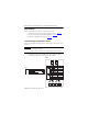
ControlLogix-XT Data Highway Plus-Remote I/O Interface Module Use this diagram to identify external features of the module.
ControlLogix-XT Data Highway Plus-Remote I/O Interface Module 9 About ControlLogix-XT Systems The ControlLogix-XT products include control and communication system components that, when used with FLEX I/O-XT products, provide a complete control system solution that can be used in environments where temperatures range from -20...70 °C (-4...158 °F). When used independently, the ControlLogix-XT system can withstand environments where the temperature ranges from -25...70 °C (-13...158 °F).
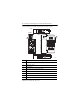
ControlLogix-XT Data Highway Plus-Remote I/O Interface Module Before You Begin Before you install your module, complete these tasks: • Set the Network Type and Node Address Switches, page 10 • Prepare the Chassis for Module Installation, page 11 • Determine Module Slot Location, page 12 Set the Network Type and Node Address Switches Before you install the module, set the network type switches for each channel.
ControlLogix-XT Data Highway Plus-Remote I/O Interface Module 11 If you set the network type to Data Highway Plus (DH+), also set the node address switches for that channel to a unique address within the range of 0…77. 2. Set the node address switches on the bottom of the module to a unique node address. BOTTOM 2 Prepare the Chassis for Module Installation Before you install the module, you must install and connect a ControlLogix-XT chassis and power supply.
ControlLogix-XT Data Highway Plus-Remote I/O Interface Module Determine Module Slot Location You can use the ControlLogix-XT chassis that suits your application requirements. The 1756-DHRIOXT modules can be: • installed in any open chassis slot. • used in multiples in one chassis, within the limits of the ControlLogix-XT power supply.
ControlLogix-XT Data Highway Plus-Remote I/O Interface Module 13 Install the Module Complete these steps to install the 1756-DHRIOXT module. ATTENTION Do not force the module into the backplane connector. If you cannot seat the module with firm pressure, check the alignment. Forcing the module into the chassis can damage the backplane connector or the module. 1. Align the circuit board with top and bottom guides in the chassis. 2. Slide the module into the chassis. CH A CH B X T OK X T 3.
ControlLogix-XT Data Highway Plus-Remote I/O Interface Module Remove or Replace the Module Complete these steps to uninstall the 1756-DHRIOXT module. 1. Push on upper and lower module tabs to disengage them. 2. Slide the module out of the chassis. CH A CH B X T OK X T If you are replacing an existing module with an identical one, and you want to resume identical system operation, you must install the new module in the same slot.
ControlLogix-XT Data Highway Plus-Remote I/O Interface Module 15 Wire the Connectors for the Module Channels Use these tables as a reference when wiring the network cable to the connectors. 6 7 8 3 4 5 1 2 8-pin Mini DIN Connector A 1756-DHRIOXT Channel A and B 2 Connectors 1 301928-M 8-pin Mini DIN Connection The 8-pin mini DIN programming terminal connection is parallel to channel A when channel A is configured for DH+ communication. Pin No.
ControlLogix-XT Data Highway Plus-Remote I/O Interface Module Connect the Programming Terminal Connect the programming terminal by using the 8-pin mini DIN connector. WARNING The local programming terminal port is intended only for temporary use and must not be connected or disconnected unless the area is assured to be nonhazardous. If you connect or disconnect the communications connector with power applied to this module or any device on the network, an electrical arc can occur.
ControlLogix-XT Data Highway Plus-Remote I/O Interface Module 17 Connect the DH+ or Remote I/O Network WARNING If you connect or disconnect the communications cable with power applied to this module or any device on the network, an electrical arc can occur. This could cause an explosion in hazardous location installations. Be sure that power is removed or the area is nonhazardous before proceeding. Connect the DH+ or Remote I/O network to the channel A or B connector as appropriate.
ControlLogix-XT Data Highway Plus-Remote I/O Interface Module Check Power Supply and Module Status After you apply chassis power, check the power supply and module status indicators to verify the module is working properly. 31931-M See the section titled Status Indicators, page 24 for more information about interpreting module status.
ControlLogix-XT Data Highway Plus-Remote I/O Interface Module 19 Alphanumeric Display Startup Sequence At powerup, the module’s alphanumeric display cycles through this sequence. • • • • • • Channel Channel Channel Channel Channel Channel A A A B B B and the network used for channel A - DH+ or RIO node address, if used for DH+ status and the network used for channel B - DH+ or RIO node address, if used for DH+ status That sequence runs continuously during normal module operation.
ControlLogix-XT Data Highway Plus-Remote I/O Interface Module Power Supply Status If the alphanumeric indicator on the 1756-DHRIO module does not cycle through alphanumeric messages on powerup, use this table, along with the sections Alphanumeric Display Codes (page 21) and Status Indicators (page 24) to determine a cause. POWER Indicator State Means Recommended Actions Off Not operating • Turn power switch ON. • Check power wiring connections. • Check fuse.
ControlLogix-XT Data Highway Plus-Remote I/O Interface Module 21 Alphanumeric Display Codes Your 1756-DHRIOXT module displays alphanumeric codes that provide diagnostic information. The alphanumeric display flashes the codes at approximately 1-second intervals. These tables describe codes and interpretations specific to the application of the module. Data Highway Plus Codes and Interpretations Code Description Recommended Action OFF LINE Data Highway Plus link is in STOP state.
ControlLogix-XT Data Highway Plus-Remote I/O Interface Module Remote I/O Codes and Interpretations Code Description Recommended Actions MUTE LINK No adapters found on remote I/O. Add an adapter to the remote I/O network. RACK OVER Rack overlap on remote I/O. Reconfigure remote I/O racks. DUPL SCAN Duplicate scanner on remote I/O. Check remote I/O adapter settings. MAX_ DEV_ Maximum devices exceeded on remote I/O. Remove devices to meet limitations on remote I/O network.
ControlLogix-XT Data Highway Plus-Remote I/O Interface Module 23 Remote I/O Codes and Interpretations Code Description Recommended Actions OK Normal operation. None. MUTE LINK No adapters found on remote I/O. Add an adapter to the remote I/O network. RACK OVER Rack overlap on remote I/O. Reconfigure remote I/O racks.
ControlLogix-XT Data Highway Plus-Remote I/O Interface Module Status Indicators Three status indicators on the module provide information about your module and the status of each channel. The following tables outline the indicator condition and the corresponding status, and explain what each condition means. OK Status Indicator State Description Recommended Actions Off The module is not operating. • Apply chassis power. • Verify module is completely inserted into chassis and backplane.
ControlLogix-XT Data Highway Plus-Remote I/O Interface Module 25 Channel A and B Indicators State Channel Mode Description Recommended Actions Off All Not on line. Place channel on line. Green RIO scanner Active RIO link. All adapter modules are present and not faulted. None - this is normal operation. DH+ Operating. None - this is normal operation. RIO scanner One or more nodes faulted or failed. Check power at other racks. DH+ No other node on the network. Check cables.
ControlLogix-XT Data Highway Plus-Remote I/O Interface Module General Specifications - 1756-DHRIOXT Attribute Value Module location 1756 ControlLogix-XT chassis, any slot Backplane current (mA) at 24V 1.7 mA Backplane current (mA) at 5V 850 mA Power dissipation, max 4.5 W Thermal dissipation, max 15.4 BTU/hr Baud rate 57.6 Kbaud 115.2 Kbaud 230.4 Kbaud Isolation voltage 30V (continuous), Basic Insulation Type Type tested at 853V AC for 60 s, DHRIO to system and DHRIO port to DHRIO port.
ControlLogix-XT Data Highway Plus-Remote I/O Interface Module 27 Environmental Specifications - 1756-DHRIOXT Attribute Value Temperature, Operating -25…70 °C (-13…158 °F) IEC 60068-2-1 (Test Ad, Operating Cold), IEC 60068-2-2 (Test Bd, Operating Dry Heat), IEC 60068-2-14 (Test Nb, Operating Thermal Shock) Temperature, Nonoperating -40…85 °C (-40…185 °F) IEC 60068-2-1 (Test Ab, Unpackaged Nonoperating Cold), IEC 60068-2-2 (Test Bb, Unpackaged Nonoperating Dry Heat), IEC 60068-2-14 (Test Na, Unpackaged
ControlLogix-XT Data Highway Plus-Remote I/O Interface Module Attribute Value Radiated RF Immunity •10V/m with 1 kHz IEC 61000-4-3 sine-wave 80% AM from 80…2000 MHz •10V/m with 200 Hz 50% Pulse 100% AM at 900 MHz •10V/m with 200 Hz 50% Pulse 100% AM at 1890 MHz •3V/m with 1 kHz sine-wave 80% AM from 2000…2700 MHz EFT/B Immunity IEC 61000-4-4 Surge Transient Immunity IEC 61000-4-5 Conducted RF Immunity IEC 61000-4-6 Publication 1756-IN638A-EN-P - March 2009 ±4 kV at 5 kHz on communication ports
ControlLogix-XT Data Highway Plus-Remote I/O Interface Module 29 Certifications - 1756-DHRIOXT Certification(1) (2) Value c-UL-us UL Listed Industrial Control Equipment, certified for US and Canada. See UL File E65584. UL Listed for Class I, Division 2 Group A,B,C,D Hazardous Locations, certified for U.S. and Canada. See UL File E194810. CE European Union 2004/108/EC EMC Directive, compliant with: •EN 61326-1; Meas./Control/Lab.
ControlLogix-XT Data Highway Plus-Remote I/O Interface Module Additional Resources These documents contain additional information concerning related Rockwell Automation products. Resource Description ControlLogix Data Highway-Plus Remote I/O Communication Interface Module Installation Instructions, publication 1756-IN003 Contains installation instructions and specifications specific to the standard ControlLogix Data Highway Plus Remote I/O module.
ControlLogix-XT Data Highway Plus-Remote I/O Interface Module 31 Notes: Publication 1756-IN638A-EN-P - March 2009
Rockwell Automation Support Rockwell Automation provides technical information on the Web to assist you in using its products. At http://support.rockwellautomation.com, you can find technical manuals, a knowledge base of FAQs, technical and application notes, sample code and links to software service packs, and a MySupport feature that you can customize to make the best use of these tools.