
Instruction Manual


Rockwell Automation Publication 1756-UM514C-EN-P - June 2014 63
Using Programming Software in DH+ Applications Chapter 4
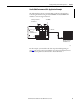
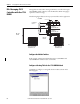
Define Connection Paths
You can configure a connection path when configuring controller-to-controller
communication or workstation-to-controller communication. The connection
path starts with the controller or the communication card in the workstation.
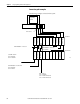
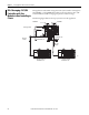
The following steps construct a communication path:
1. Separate the number or address entered in each step with a comma. All
numbers are in decimal by default. You can enter any number, other than
an Ethernet IP address, in another base by using the IEC-1131 prefix
(8# for octal, 16# for hexadecimal). Ethernet IP addresses are decimal
numbers separated by periods.
2. To construct the path, you enter one or more path segments that lead to the
controller. Each path segment takes you from one module to another
module over the ControlBus backplane or over a DH+, ControlNet, or
Ethernet networks.
You can have a maximum of 8 paths leading to the controller.
Each path segment contains two numbers: x,y
Where:
If you have multiple path segments, you must also separate each path segment
with a comma (,).
This Is
x
number of the type of port you use to exit from the module you are at:
0 DH+ port from a KT card
1 backplane from any 1756 module
2 RS232 port from a 1756-L1 controller
2 ControlNet port from a KTC card or a 1756-CNB module
2 Ethernet port from a 1756-ENET module
2 DH+ port over channel A from a 1756-DHRIO or 1756-DHRIOXT module
3 DH+ port over channel B from a 1756-DHRIO or 1756-DHRIOXT module
, separates the first number and second number of the path segment
y address of the module you are going to
For Address means:
ControlBus backplane slot number (0-16 decimal)
DF1 network station address (0-254)
ControlNet network node number (1-99 decimal)
DH+ network node number (0-77 octal)
Ethernet network IP address (four decimal numbers
separated by periods)