
Instruction Manual


Rockwell Automation Publication 1756-UM514C-EN-P - June 2014 153
Chapter 13
Troubleshooting the Module
What This Chapter Contains
This chapter describes your module’s diagnostics and methods of
troubleshooting your module.
Check Power Supply and
Module Status
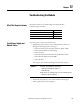
On power-up, three events occur simultaneously:
• Alphanumeric status indicator on the module illuminates and cycles
through the following sequence of messages:
– Channel A and the network used for channel A - DH+ or RIO
– Channel A node address, if used for DH+
– Channel A status
– Channel B and the network used for channel B - DH+ or RIO
– Channel B node address, if used for DH+
– Channel B status
This sequence runs continuously during normal module operation.
• Module OK status indicator shows solid red and then flashes green
• Power supply indicator shows solid green
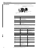
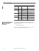
Topic Page
Check Power Supply and Module Status 153
Status Indicators 154
Minimizing False Received Frame with Bad CRC Messages 156
EXAMPLE
For example, if your module uses the following:
• Channel A for DH+ with node address 14
• Channel B for RIO
and the channels are operating properly, you see the following sequence:
• A DH, A#14, A OK, B IO, SCAN, B OK