User Manual ControlLogix Data Highway Plus-Remote I/O Communication Interface Module Catalog Numbers 1756-DHRIO, 1756-DHRIOXT
Important User Information Read this document and the documents listed in the additional resources section about installation, configuration, and operation of this equipment before you install, configure, operate, or maintain this product. Users are required to familiarize themselves with installation and wiring instructions in addition to requirements of all applicable codes, laws, and standards.
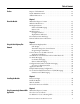
Summary of Changes This manual contains new and updated information. Changes throughout this revision are marked by change bars, as shown to the right of this paragraph. New and Updated Information This table contains the changes made to this revision.
Summary of Changes Notes: 4 Rockwell Automation Publication 1756-UM514C-EN-P - June 2014
Table of Contents Preface Purpose of This Manual . . . . . . . . . . . . . . . . . . . . . . . . . . . . . . . . . . . . . . . . . . 11 Studio 5000 Environment . . . . . . . . . . . . . . . . . . . . . . . . . . . . . . . . . . . . . . . . 12 Additional Resources . . . . . . . . . . . . . . . . . . . . . . . . . . . . . . . . . . . . . . . . . . . . . 12 Chapter 1 About the Module What This Chapter Contains . . . . . . . . . . . . . . . . . . . . . . . . . . . . . . . . . . . . . What the Module Does. .
Table of Contents What Is a Routing Table? . . . . . . . . . . . . . . . . . . . . . . . . . . . . . . . . . . . . . Pyramid Integrator Emulation . . . . . . . . . . . . . . . . . . . . . . . . . . . . . . . . . ControlLogix Routing . . . . . . . . . . . . . . . . . . . . . . . . . . . . . . . . . . . . . . . . Create the Routing Table . . . . . . . . . . . . . . . . . . . . . . . . . . . . . . . . . . . . . . . . . Configure the Controller Slot . . . . . . . . . . . . . . . . . . . . . . . . . . . . . . .
Table of Contents Configure the Module Switches . . . . . . . . . . . . . . . . . . . . . . . . . . . . . . . Configure a Controller Slot for the Module . . . . . . . . . . . . . . . . . . . . DH+ Messaging: SLC 5/04 to a ControlLogix Controller with Multiple ControlLogix Chassis. . . . . . . . . . . . . . . . . . . . . . . . . . . . . . . . . . . . Configure the Module Switches . . . . . . . . . . . . . . . . . . . . . . . . . . . . . . . Configure a Routing Table for the Module . . . . . . . . . . . . .
Table of Contents Configure the Data Exchange Rate Between the Modules and a Controller. . . . . . . . . . . . . . . . . . . . . . . . . . . . . . . . . . . . . . . . . . . . . . . . . Requested Packet Interval (RPI) . . . . . . . . . . . . . . . . . . . . . . . . . . . . . . RIO Scanner Status Update Rate with the Module in a Local Chassis . . . . . . . . . . . . . . . . . . . . . . . . . . . . . . . . . . . . . . . . . . . . RIO Scanner Status Update Rate with the Module in a Remote Chassis. . . . . . .
Table of Contents Configure the Second Module. . . . . . . . . . . . . . . . . . . . . . . . . . . . . . . . Configure the Second FLEX Adapter . . . . . . . . . . . . . . . . . . . . . . . . . Scan 1771 Remote I/O Adapters through a 1756-DHRIO or 1756-DHRIOXT Module in a Remote Chassis. . . . . . . . . . . . . . . . . . . . Configure the 1756-DHRIO or 1756-DHRIOXT Module Switches . . . . . . . . . . . . . . . . . . . . . . . . . . . . . . . . . . . . . . . . . . . . Configure First 1756-CNB Module. . . . .
Table of Contents Appendix B Application Guidelines and Tips Cached and Uncached Connections . . . . . . . . . . . . . . . . . . . . . . . . . . . . . . Cached Connections. . . . . . . . . . . . . . . . . . . . . . . . . . . . . . . . . . . . . . . . . Uncached Connections . . . . . . . . . . . . . . . . . . . . . . . . . . . . . . . . . . . . . . ControlLogix Controller Constraints . . . . . . . . . . . . . . . . . . . . . . . . . . . . . Message Manager. . . . . . . . . . . . . . . . . . . . . . . . . .
Preface Purpose of This Manual This manual describes how to understand, configure, and troubleshoot your ControlLogix® Data Highway Plus™ Remote I/O (1756-DHRIO) communication interface module and ControlLogix Data Highway Plus Remote I/O extreme temperature communication interface module. This manual also provides step-by-step procedures on how to: • use the 1756-DHRIO and 1756-DHRIOXT modules to send DH+™ messages between ControlLogix controllers, PLC and SLC controllers in DH+ applications.
Preface Studio 5000 Environment The Studio 5000 Automation Engineering & Design Environment™ combines engineering and design elements into a common environment. The first element in the Studio 5000® environment is the Studio 5000 Logix Designer™ application. The Logix Designer application is the rebranding of RSLogix™ 5000 software and continues to be the product to program Logix5000™ controllers for discrete, process, batch, motion, safety, and drive-based solutions.
Chapter 1 About the Module What This Chapter Contains What the Module Does This chapter describes the 1756-DHRIO and 1756-DHRIOXT modules and what you must know and do before you begin to use it.
Chapter 1 About the Module Routing Limitations The modules can route a message through as many as four communication networks and three chassis. This limit applies to only the routing of a message and not to the total number of networks or chassis in a system. DH+ and CIP Messaging The modules allow an information exchange between devices, such as ControlLogix controllers, PLC and SLC controllers.
About the Module Chapter 1 Remote I/O When a channel on the module is configured for Remote I/O, the module acts as a scanner for the remote I/O network. The ControlLogix controller communicates to the module’s remote I/O scanner to send and receive the I/O on the remote I/O network. The figure shows an example system.
Chapter 1 About the Module The figure shows the external features of the 1756-DHRIO and 1756-DHRIOXT modules.
About the Module Chapter 1 Configure Switches Before installing the module, you must set the network type switches for DH+ or RIO, depending on your application. For a channel configured as DH+, you must also select a node address within the range of 00-77. Node addresses are set and displayed in octal. IMPORTANT If your module uses the 230k DH+ network (that is Channel A switch set to 3), Channel B is disabled. Also, node address switches do not apply if you are using remote I/O.
Chapter 1 About the Module Alphanumeric Indicators Alphanumeric status indicator illuminates and cycles through a sequence of messages (described in the table on the following page). H+/RIO CHA CHB OK 43241 At power-up the module’s alphanumeric display begins a cycle through the following sequences.
About the Module Prevent Electrostatic Discharge Chapter 1 The Data Highway Plus module is sensitive to electrostatic discharge. ATTENTION: This equipment is sensitive to electrostatic discharge, which can cause internal damage and affect normal operation. Follow these guidelines when you handle this equipment: • Touch a grounded object to discharge potential static. • Wear an approved grounding wriststrap. • Do not touch connectors or pins on component boards.
Chapter 1 About the Module Notes: 20 Rockwell Automation Publication 1756-UM514C-EN-P - June 2014
Chapter 2 Using the Data Highway Plus Network This chapter describes the basics of Data Highway Plus (DH+) and the operation of a DH+ network.
Chapter 2 Using the Data Highway Plus Network Link Design When you design your DH+ link, use good design practices, including laying out the link before installation. We also recommend you consider the following when designing your DH+ link: • All performance requirements • Maintenance • Possible future changes to the link Use a1770-CD (Belden 9463) cable to connect your 1756-DHRIO module to DH+. Use a Belden 89463 cable to connect your 1756-DHRIOXT module to DH+.
Using the Data Highway Plus Network Chapter 2 Programming Terminal Port The programming terminal connector is the same physical link as Channel A. Programming Terminal Connector Channel A 41279 IMPORTANT When configuring the module switches, remember the programming terminal connector can be used only if Channel A is set for DH+. The following table lists the devices you can connect to a DH+ link. Connect Devices to the DH+ Network To: You can use: Cat. No.
Chapter 2 Using the Data Highway Plus Network Application Guidelines Consider the following application guidelines when configuring a DH+ link for your system: • Minimize the number of DH+ nodes to achieve acceptable response times. Keep in mind the size and frequency of messages exchanged between devices. • Limit the number of stations on your network when you are trying to achieve the fastest control response time. Establish separate DH+ networks to bring-on additional stations.
Using the Data Highway Plus Network Two Methods of Communication Over a DH+ Network Chapter 2 The 1756-DHRIO and 1756-DHRIOXT modules act as a bridge for two methods of communication. These methods are: • DH+ Messaging • Control and Information Protocol (CIP) Messaging The following table lists the devices that support each communication method.
Chapter 2 Using the Data Highway Plus Network controller slot for port A is configured to “0”, the message is forwarded to the ControlLogix controller in slot 0.
Using the Data Highway Plus Network Chapter 2 Sending Local DH+ Messages on DH+ If a 1756-DHRIO channel receives a DH+ message with a destination link ID=0 from a ControlLogix controller in the same chassis, the module sends the message as a local DH+ message. IMPORTANT The target of the DH+ message must be on the same DH+ link as the 1756DHRIO and 1756-DHRIOXT modules sending the message.
Chapter 2 Using the Data Highway Plus Network • Assign DH+ node numbers. • Use the Studio 5000 environment to enter the controller slot or execute the default for the controller slot for each channel configured for DH+. IMPORTANT These configuration steps must be done for each 1756-DHRIO or 1756-DHRIOXT in the your system. Remote DH+ Messaging Devices use remote DH+ messaging to communicate between devices on physically separate networks.
Using the Data Highway Plus Network Chapter 2 The following figure shows an example of remote DH+ messaging between PLC processor A and PLC processor B.
Chapter 2 Using the Data Highway Plus Network 1756-DHRIO and 1756-DHRIOXT modules enable devices, such as PLC-5s, to use “DH+ Remote Addressing” for messaging. You must use RSLinx to configure your routing table.
Using the Data Highway Plus Network Chapter 2 1756-DHRIO and 1756-DHRIOXT modules, although this is transparent to the user. The 1756-DHRIO and 1756-DHRIOXT modules support a total of 32 CIP connections per DH+ channel. These connections are made when devices want to send a DH+ message out of a 1756-DHRIO or 1756-DHRIOXT module’s DH+ channel and are made by the 1756-DHRIO or 1756-DHRIOXT module when it receives DH+ message traffic.
Chapter 2 Using the Data Highway Plus Network Configuration Information in DH+ Messaging When you are using DH+ messaging, you must use the default configuration or write configuration for your application. The following configuration information is stored in the nonvolatile (NVS) memory on your 1756-DHRIO and 1756-DHRIOXT modules when you apply configuration by using the Studio 5000 environment: • Any routing table that can be needed to send DH+ messages through the module.
Using the Data Highway Plus Network Chapter 2 When an error occurs while sending a message to a remote link, it appears to the sending station as an application timeout because error messages are not routed back. When an error occurs during routing, it can be dropped. Application Timeout For example, if a PLC 5/40 processor sends a message to a PLC processor, and the PLC-5/25 processor’s buffers are full, three things happen: • The PLC-5/25 processor refuses the message because the buffers are full.
Chapter 2 Using the Data Highway Plus Network The following figure shows an example DH+ routing configuration. Example DH+ Routing Configuration Node numbers on DH+ are given in octal. Node numbers on ControlNet network and slot numbers in ControlLogix chassis are given in decimal. Links IDs for all networks are given in decimal. 1756-DHRIO and 1756-DHRIOXT Modules Ch. A Node: 015 Ch.
Using the Data Highway Plus Network Use Control and Information Protocol (CIP) Messaging Chapter 2 Control and Information Protocol (CIP) is the communication mechanism on ControlLogix chassis, ControlNet network and Ethernet with the Encapsulation Protocol (EPIC) protocol. Like DH+ messaging, CIP supports communication between devices on the same link and physically separate links. However, CIP Messaging uses another method to route messages than DH+ Messaging.
Chapter 2 Using the Data Highway Plus Network Notes: 36 Rockwell Automation Publication 1756-UM514C-EN-P - June 2014
Chapter 3 Installing the Modules Topic Page Before You Begin 40 Install the Module 41 Wire the Module 42 Network Connectors and Cable 43 You can install or remove the module while chassis power is applied. ATTENTION: Environment and Enclosure This equipment is intended for use in a Pollution Degree 2 industrial environment, in overvoltage Category II applications (as defined in IEC 60664-1), at altitudes up to 2000 m (6562 ft) without derating.
Chapter 3 Installing the Modules North American Hazardous Location Approval The following information applies when operating this equipment in hazardous locations. Informations sur l’utilisation de cet équipement en environnements dangereux. Products marked "CL I, DIV 2, GP A, B, C, D" are suitable for use in Class I Division 2 Groups A, B, C, D, Hazardous Locations and nonhazardous locations only.
Installing the Modules Chapter 3 European Hazardous Location Approval The following applies when the product bears the Ex Marking. This equipment is intended for use in potentially explosive atmospheres as defined by European Union Directive 94/9/EC and has been found to comply with the Essential Health and Safety Requirements relating to the design and construction of Category 3 equipment intended for use in Zone 2 potentially explosive atmospheres, given in Annex II to this Directive.
Chapter 3 Installing the Modules Before You Begin Follow these procedures before installing the module. ATTENTION: If this equipment is used in a manner not specified by the manufacturer, the protection provided by the equipment may be impaired. 1. Identify the module features, as shown.
Installing the Modules Chapter 3 If the network type is DH+, you must also set the node address switches for that channel. IMPORTANT If you are using the remote I/O network, do not set node address switches. For each channel, you can select a node address within the range of 00…77. 4. Determine module slot location. This example shows chassis slot numbering in a 4-slot chassis. Slot 0 is the first slot and is the left most slot in the rack (the first slot to the right of the power supply).
Chapter 3 Installing the Modules Wire the Module Wire the connectors for the module channels. WARNING: If you connect or disconnect the communications cable with power applied to this module or any device on the network, an electrical arc can occur. This could cause an explosion in hazardous location installations. Be sure that power is removed or the area is nonhazardous before proceeding. .
Installing the Modules Chapter 3 5. Apply chassis power. 6. Check power supply and module status. Network Connectors and Cable The following network connectors and cable are available for the modules.
Chapter 3 Installing the Modules Notes: 44 Rockwell Automation Publication 1756-UM514C-EN-P - June 2014
Chapter 4 Using Programming Software in DH+ Applications What This Chapter Contains Select the Correct Software This chapter describes how to use programming software with your 1756-DHRIO and 1756-DHRIOXT modules in DH+ applications, including a brief discussion of how to use each. For more information on these software, see the online help in each.
Chapter 4 Using Programming Software in DH+ Applications Use RSLinx to Create a Routing Table DH+ protocols do not use the Control and Information Protocol (CIP), the communication protocol used in the ControlLogix architecture. The 1756-DHRIO and 1756-DHRIOXT modules are the transition point from the DH+ network to ControlLogix. In this capacity, the 1756-DHRIO and 1756-DHRIOXT modules serve as the DH+ message source and require a full message route, or path, to deliver the message.
Using Programming Software in DH+ Applications Chapter 4 For example, the Pyramid Integrator system shown in the following figure uses the routing tables described in the following tables.
Chapter 4 Using Programming Software in DH+ Applications An equivalent routing (via the DH+ network) with ControlLogix is shown in the following figure.
Using Programming Software in DH+ Applications Create the Routing Table Chapter 4 To create a routing table for your application, follow these steps: 1. Start RSLinx. 2. Browse the network. 3. Use the left-side navigation bar to see your DH+ application, as shown in the following example. 1. Expand the configuration tree until your application appears on the right side of the dialog box. 2. Right-click the 1756-DHRIO or 1756DHRIOXT module’s icon to see the menu. 3. Click Module Configuration. 4.
Chapter 4 Using Programming Software in DH+ Applications 5. You must assign link IDs, as shown below. 1. Right-click the 1756-DHRIO module to see the menu. 2. Click Edit Module. IMPORTANT Keep track of your Link ID assignments. You need the Link ID values when you send messages via Studio 5000 environment software. 6. To assign a Link ID for the chassis backplane, follow the procedure described in step 5. When you are finished assigning Link IDs, your dialog box will look similar to the one below.
Using Programming Software in DH+ Applications Chapter 4 When the routing table is downloaded, RSLinx returns to the Browsing screen. This completes the routing table creation process. Configure the Controller Slot The Controller Slot is the physical location of a ControlLogix controller in a DH+ application. The default setting is slot 0. If necessary, use the Channel Configuration tab to change the Controller Slot number. 1. Change the Controller slot. 2. Click OK.
Chapter 4 Using Programming Software in DH+ Applications To do this, use the 1756-ENET module to connect to a second ControlLogix chassis that contains the second 1756-DHRIO or 1756-DHRIOXT module, as shown in the following figure.
Using Programming Software in DH+ Applications Chapter 4 4. Add a message instruction (MSG) to the new rung. Click here to add a MSG. 5. Change the MSG instruction Control. Type the new Control value here. This example uses a Control of MG10:0. 6. Configure the MSG instruction on the Setup dialog box. Double-click Setup Screen to access the message instruction dialog box.
Chapter 4 Using Programming Software in DH+ Applications Studio 5000 Environment DH+ Application Example The following figure shows an example DH+ application where PLC-5/25 processor A writes data, via a message instruction and the 1756-DHRIO or 1756-DHRIOXT module, to PLC-5 processor B.
Using Programming Software in DH+ Applications Use RSLogix 500 Chapter 4 RSLogix 500 software is required to send read/write message instructions from SLC-500s in DH+ applications. To send messages, follow these steps: IMPORTANT This section offers a brief description of how to send a message via RSLogix 500 software. For a full description of how to use the software, see the online help. 1. Start the RSLogix 500 software. 2. Begin a new project or open a project. 3.
Chapter 4 Using Programming Software in DH+ Applications 5. Change the MSG instruction Control. Type the new Control value here. This example uses a Control of N7:20. 6. Configure the MSG instruction on the Setup dialog box. Double-click Setup Screen.
Using Programming Software in DH+ Applications Chapter 4 RSLogix 500 DH+ Application Example The following figure shows an example DH+ application that includes SLC-5 processors using the 1756-DHRIO and 1756-DHRIOXT modules to write message instructions.
Chapter 4 Using Programming Software in DH+ Applications Use the Studio 5000 Environment The Studio 5000 environment is required to send read/write message instructions from a ControlLogix controller in DH+ applications. To send messages, follow these steps: IMPORTANT You are not required to add the 1756-DHRIO or 1756-DHRIOXT module to the Controller Organizer to send message instructions from a ControlLogix controller in a DH+ application. 1. Start the Studio 5000 environment. 2.
Using Programming Software in DH+ Applications Chapter 4 5. Add a new tag to the MSG instruction. 1. Right-click the question mark (?) the menu. 2. Click New Tag. 6. Name and define the new tag. 1. Name the tag. 2. Make sure this tag is of the MESSAGE type. 7. Access the message type configuration and communication parameters. Double-click the ellipsis (…) button.
Chapter 4 Using Programming Software in DH+ Applications 8. Change the message configuration. 1. Choose the Message Type from the pull-down list. 2. Choose the Source Element from the pull-down list if the tag exists. If the tag does not exist, use the New Tag feature (shown below) to create it. 3. Type the Number of Elements being written. 4. Type the Destination Element. In this example, the Destination Element is a PLC-5 data table. If you create a Tag, you must: 1. Name the tag. 2.
Using Programming Software in DH+ Applications Chapter 4 Studio 5000 Environment DH+ Application Example The following figure shows an example DH+ application that includes a ControlLogix controller using the 1756-DHRIO and 1756-DHRIOXT modules to write message instructions. ControlLogix Controller Slot Number: 0 1756-DHRIO DH+ Link Channel A Node Number: 010 PLC-5/60 controller A Node Number: 015 41283 For this example, you must follow the basic steps described beginning on page 58.
Chapter 4 Using Programming Software in DH+ Applications Configuration Pop-Up Dialog Box Communication Pop-Up Dialog Box 1 represents the ControlLogix backplane (as the message leaves the ControlLogix controller) 62 Rockwell Automation Publication 1756-UM514C-EN-P - June 2014 3 represents the location of the 1756DHRIO module (that is slot 3)
Using Programming Software in DH+ Applications Define Connection Paths Chapter 4 You can configure a connection path when configuring controller-to-controller communication or workstation-to-controller communication. The connection path starts with the controller or the communication card in the workstation. The following steps construct a communication path: 1. Separate the number or address entered in each step with a comma. All numbers are in decimal by default.
Chapter 4 Using Programming Software in DH+ Applications Connection path examples The following examples are based on this system: DH+ Ethernet Control- serial Programming Terminal ControlNet = port 2 DH+ module Local Chassis Ethernet module ControlNet module controller module DH+ module ControlNet module Ethernet module DH+ Ethernet ControlNet Serial DH+ = Port 0 ControlNet = Node 49 Ethernet IP Address = 21.21.21.21 Ethernet IP Address = 34.34.34.
Using Programming Software in DH+ Applications Network serial ControlNet Ethernet Example Programming terminal to controller module in logical rack. Use DF1 Upload logic from local controller (controller is directly connected to the programming terminal). Programming terminal to controller module in remote rack. Use DF1 (connected to controller in local rack) Use ControlNet to bridge to remote chassis. Chapter 4 Description Configure DF1 driver. Leave connection path blank. Configure the DF1 driver.
Chapter 4 Network DH+ ControlNet Ethernet DH+ 66 Using Programming Software in DH+ Applications Example Program the controller in slot 9 of the remote chassis. Go from DH+ to the local chassis. Bridge to the remote chassis over ControlNet. Description Configure the DH+ driver.
Chapter 5 Messaging Between PLC-5 and SLC 5/04 Controllers This chapter describes how to use DH+ messaging between PLC-5 and SLC 5/04 controllers.
Chapter 5 Messaging Between PLC-5 and SLC 5/04 Controllers DH+ Messaging: PLC-5 Controllers with One 1756DHRIO This application sends a DH+ message from PLC-5 controller A through a 1756-DHRIO module to PLC-5 controller B. Remote DH+ messaging is required to send the message. The following figure illustrates the steps you must follow in this application.
Messaging Between PLC-5 and SLC 5/04 Controllers Chapter 5 Configure Message Instructions Use RSLogix 5 to configure the remote PLC-5 message instructions being sent to ControlLogix controller B. The following figure shows message instruction for this example.
Chapter 5 Messaging Between PLC-5 and SLC 5/04 Controllers This application sends a DH+ message from SLC 5/04 controller A through two 1756-DHRIO or 1756-DHRIOXT modules in the same chassis to SLC 5/04 controller B. Remote DH+ messaging is required to send the message. DH+ Messaging: SLC 5/04 Controllers with Two Modules in One ControlLogix Chassis The following figure illustrates the steps you must use in this application.
Messaging Between PLC-5 and SLC 5/04 Controllers Chapter 5 Configure the Module Switches In this application, Channel B on the 1756-DHRIO and 1756-DHRIOXT modules must be set for DH+. Configure a Routing Table for the 1756-DHRIO Modules Use RSLinx to configure a routing table for the 1756-DHRIO and 1756-DHRIOXT modules. The following figure shows the routing table for this example.
Chapter 5 Messaging Between PLC-5 and SLC 5/04 Controllers Configure Message Instructions Use RSLogix 500 software to configure the SLC-500 controller message instructions, as shown in the following figure. IMPORTANT 72 RSLogix 500 software displays Nodes and link IDs in decimal. Also, in this application, a remote bridge address is not required.
Messaging Between PLC-5 and SLC 5/04 Controllers Chapter 5 This application sends a DH+ message from PLC-5 controller A through 1756-DHRIO and 1756-DHRIOXT modules in separate chassis over ControlNet to PLC-5 controller B. Remote DH+ messaging is required to send the message. DH+ Messaging: PLC-5 Controllers with Multiple ControlLogix Chassis The following figure illustrates the steps you must use in this application.
Chapter 5 Messaging Between PLC-5 and SLC 5/04 Controllers Configure the Module Switches In this application, you must set switches on the 1756-DHRIO and 1756-DHRIOXT modules for DH+ and the switches on the 1756-CNB modules to Node addresses 22 for the 1756-CNB module in system number 1 and 23 for the 1756-CNB module in system number 2. IMPORTANT The switches on the 1756-CNB modules must match the information in the module routing tables.
Messaging Between PLC-5 and SLC 5/04 Controllers Chapter 5 Configure Routing Tables for the Modules You must configure routing tables for each 1756-DHRIO and 1756-DHRIOXT module in this example. The following figure shows the routing table for the 1756-DHRIO and 1756-DHRIOXT modules in ControlLogix system number 1 this example. The following figure shows the routing table for the 1756-DHRIO and 1756-DHRIOXT modules in ControlLogix system number 2 this example.
Chapter 5 Messaging Between PLC-5 and SLC 5/04 Controllers Configure Message Instructions Use RSLogix 5 software to configure the remote PLC-5 message instructions being sent to ControlLogix controller B, as shown in the following figure.
Messaging Between PLC-5 and SLC 5/04 Controllers DH+ Messaging: PLC-5 to PLC-5/C Controllers on the ControlNet Network Chapter 5 This application sends a DH+ message from PLC-5 controller A through 1756-DHRIO and 1756-CNB modules to PLC-5C controller B on the ControlNet network. Remote DH+ messaging is required to send the message. The following figure illustrates the steps you must use in this application.
Chapter 5 Messaging Between PLC-5 and SLC 5/04 Controllers Configure the Module Switches In this application, you must set switches on the 1756-DHRIO and 1756-DHRIOXT modules for DH+ and the switches on the 1756-CNB module to Node address 22. Configure a Routing Table for the 1756-DHRIO Module Use RSLinx to configure a routing table for the modules. The following figure shows the routing table for this example.
Chapter 6 Messaging Between PLC-5 or SLC 5/04 Controllers and ControlLogix Controllers What This Chapter Contains This chapter describes how to use DH+ messaging between PLC-5 or SLC 5/04 controllers and a ControlLogix controller.
Chapter 6 Messaging Between PLC-5 or SLC 5/04 Controllers and ControlLogix Controllers DH+ Messaging: PLC-5 Controllers to One ControlLogix Controller with One ControlLogix Chassis This application sends a DH+ message from PLC-5/60 controller A through a 1756-DHRIO or 1756-DHRIOXT module to ControlLogix controller B. Local DH+ messaging can be used to send the message. IMPORTANT Local DH+ messaging can send only DH+ messages to one ControlLogix controller per DH+ channel.
Messaging Between PLC-5 or SLC 5/04 Controllers and ControlLogix Controllers Chapter 6 Configure the Module Switches In this example, Channel A on the 1756-DHRIO and 1756-DHRIOXT modules must be set for DH+. Configure a Controller Slot for the 1756-DHRIO Module In this example, the controller is not in the default slot (slot 0) of the ControlLogix chassis. You must use RSLinx software to configure a controller slot for the 1756-DHRIO and 1756-DHRIOXT modules as shown in the following figure.
Chapter 6 Messaging Between PLC-5 or SLC 5/04 Controllers and ControlLogix Controllers Configure Message Instructions You must use RSLogix 5 software to configure the PLC-5 message instructions. The following figure shows a message instruction necessary for this example.
Messaging Between PLC-5 or SLC 5/04 Controllers and ControlLogix Controllers DH+ Messaging: PLC-5 to Multiple ControlLogix Controllers in One ControlLogix Chassis Chapter 6 This application sends a DH+ message from PLC-5/60 controller A through a 1756-DHRIO and 1756-DHRIOXT modules to multiple ControlLogix controllers. IMPORTANT In this example, we use local and remote DH+ messaging to send DH+ messages. Local DH+ messaging is used to send a message to ControlLogix controller A.
Chapter 6 Messaging Between PLC-5 or SLC 5/04 Controllers and ControlLogix Controllers Configure the Module Switches In this example, Channel A on the 1756-DHRIO and 1756-DHRIOXT modules must be set for DH+. Configure a Controller Slot for the Module In this example, the controller is not in the default slot (slot 0) of the ControlLogix chassis. You must use RSLinx software to configure a controller slot for the 1756-DHRIO and 1756-DHRIOXT modules.
Messaging Between PLC-5 or SLC 5/04 Controllers and ControlLogix Controllers DH+ Messaging: SLC 5/04 to a ControlLogix Controller with Multiple ControlLogix Chassis Chapter 6 This application sends a DH+ message from SLC 5/04 controller A through a 1756-DHRIO or 1756-DHRIOXT module in ControlLogix system number 1 to a 1756-DHRIO or 1756-DHRIOXT module in ControlLogix system number 2 to ControlLogix controller B. Remote DH+ messaging is required to send the message.
Chapter 6 Messaging Between PLC-5 or SLC 5/04 Controllers and ControlLogix Controllers Configure the Module Switches In this application, you must set switches on the 1756-DHRIO and 1756-DHRIOXT modules for DH+ and the switches on the 1756-CNB modules to the correct node addresses. The 1756-CNB module in system number 1 uses node address 22 and the 1756-CNB module in system number 2 uses node address 23.
Messaging Between PLC-5 or SLC 5/04 Controllers and ControlLogix Controllers Chapter 6 Configure Message Instructions Use RSLogix 500 software to configure the SLC-500 controller message instructions. The following figure shows a message instruction necessary for this example. IMPORTANT RSLogix 500 software displays nodes and link IDs in decimal. Also, in this application, a remote bridge address is not required.
Chapter 6 Messaging Between PLC-5 or SLC 5/04 Controllers and ControlLogix Controllers Notes: 88 Rockwell Automation Publication 1756-UM514C-EN-P - June 2014
Chapter 7 Messaging Between ControlLogix Controllers and PLC-5 or SLC 5/04 Controllers What This Chapter Contains This chapter describes how to use DH+ messaging between a ControlLogix controller and PLC or SLC controller. Topic Page Local DH+ Messaging: ControlLogix Controller in One Chassis to a PLC-5 90 DH+ Messaging: ControlLogix Controller to a SLC 5/04 Controller over ControlNet and DH+ Networks 92 IMPORTANT The examples use PLC-5 and SLC 5/04 controllers to send DH+ messages.
Chapter 7 Messaging Between ControlLogix Controllers and PLC-5 or SLC 5/04 Controllers Local DH+ Messaging: ControlLogix Controller in One Chassis to a PLC-5 This application sends a DH+ message from a ControlLogix controller A through a 1756-DHRIO or 1756-DHRIOXT module to a PLC-5 controller B on a DH+ link. Local DH+ messaging can be used to send the message. In this case, local DH+ messaging is used. The following figure illustrates the steps you must use in this application.
Messaging Between ControlLogix Controllers and PLC-5 or SLC 5/04 Controllers Chapter 7 Configure the Module Switches In this application, channel A on the 1756-DHRIO and 1756-DHRIOXT modules must be set for DH+. Configure Message Instructions Use the Studio 5000 environment to configure the ControlLogix controller message instructions. The following figure shows the message instruction tabs necessary for this example.
Chapter 7 Messaging Between ControlLogix Controllers and PLC-5 or SLC 5/04 Controllers DH+ Messaging: ControlLogix Controller to a SLC 5/04 Controller over ControlNet and DH+ Networks This application sends a DH+ message from ControlLogix controller A to SLC 5/04 controller B over ControlNet and DH+ networks. Remote DH+ messaging is used to send the message in this application. The following figure illustrates the steps you must use in this application.
Messaging Between ControlLogix Controllers and PLC-5 or SLC 5/04 Controllers Chapter 7 Configure the Module Switches In this application, you must set switches on the 1756-DHRIO and 1756-DHRIOXT modules for DH+ and the switches on the 1756-CNB modules to the correct node addresses. The 1756-CNB module in system number 1 uses node address 22 and the 1756-CNB module in system number 2 uses node address 23.
Chapter 7 Messaging Between ControlLogix Controllers and PLC-5 or SLC 5/04 Controllers Configure Message Instructions Use the Studio 5000 environment to configure the ControlLogix controller message instructions. The following figure shows the message instruction tabs necessary for this example.
Chapter 8 Messaging Between ControlLogix Controllers What This Chapter Contains This chapter describes how to use Control and Information Protocol (CIP) messaging between ControlLogix controllers with the1756-DHRIO and 1756-DHRIOXT modules. Topic Page CIP Messaging Between ControlLogix Controllers over One Link 95 CIP Message Routing Between ControlLogix Controllers over Two Links 97 Each of the following examples explains what steps you must take to perform the described operations.
Chapter 8 Messaging Between ControlLogix Controllers Configure the Module Switches In this application, Channel B on the 1756-DHRIO and 1756-DHRIOXT modules must be set for DH+. Configure Message Instructions Use the Studio 5000 environment to configure the ControlLogix controller message instructions. The following figure shows the message instructions necessary for this example.
Messaging Between ControlLogix Controllers Chapter 8 This application sends a CIP message from ControlLogix controller A through a 1756-DHRIO of 1756-DHRIOXT module to ControlLogix controller B controller B over two links. CIP Message Routing Between ControlLogix Controllers over Two Links The following figure illustrates the steps you must use in this application.
Chapter 8 Messaging Between ControlLogix Controllers Configure the Module Switches In this application, Channel A on the first and last 1756-DHRIO or 1756-DHRIOXT modules must be set for DH+. The channels on the second 1756-DHRIO or 1756-DHRIOXT module must be set for DH+. Configure Message Instructions Use the Studio 5000 environment to configure the ControlLogix controller message instructions. The following figure shows the message instructions necessary for this example.
Chapter 9 Using the 1756-DHRIO and 1756-DHRIOXT Modules in Remote I/O Applications What This Chapter Contains This chapter describes the basic procedures of using the 1756-DHRIO and 1756-DHRIOXT modules in remote I/O scanner mode and configuring a remote I/O network.
Chapter 9 Using the 1756-DHRIO and 1756-DHRIOXT Modules in Remote I/O Applications Introduction to Remote I/O The remote I/O system lets you control I/O devices that are not in the controller’s chassis. A 1756-DHRIO channel, configured as a remote I/O scanner, transfers discrete and block-transfer data between a ControlLogix controller and remote I/O devices. The following figure shows an example of a remote I/O system.
Using the 1756-DHRIO and 1756-DHRIOXT Modules in Remote I/O Applications Select Devices that You Can Connect Chapter 9 The following table lists some of the devices you can use on a remote I/O network as an adapter. Category Product Cat. No.
Chapter 9 Using the 1756-DHRIO and 1756-DHRIOXT Modules in Remote I/O Applications Design a Remote I/O Network Designing a remote I/O network requires applying network and cable design guidelines. Network Design Guidelines Follow these rules as you design a remote I/O network: • All devices connected to a remote I/O network must communicate by using the same communication rate. The following rates are available for remote I/O: – 57.6kbps – 115.2kbps – 230.
Using the 1756-DHRIO and 1756-DHRIOXT Modules in Remote I/O Applications Chapter 9 Trunk Line/Drop Line Considerations When using a trunk line/drop line configuration, use 1770-SC station connectors and follow these cable-length guidelines: • The trunk line-cable length depends on the communication rate of the link. • The drop-cable length uses a maximum of 30.4 m (100 cable-ft.). For daisy chain configurations, use the following table to determine the total cable length you can use.
Chapter 9 Using the 1756-DHRIO and 1756-DHRIOXT Modules in Remote I/O Applications Module Operation in a Remote I/O Application The 1756-DHRIO and 1756-DHRIOXT modules provide two configurable channels that can send and receive messages over DH+ or scan remote I/O devices. You must set the rotary switches on the module to use the 1756-DHRIO or 1756-DHRIOXT module in a remote I/O application. Set the channel you want to use for Remote I/O to 1.
Using the 1756-DHRIO and 1756-DHRIOXT Modules in Remote I/O Applications Chapter 9 Exchange I/O Data Between the Module and Adapters I/O data is exchanged between the 1756-DHRIO or 1756-DHRIOXT module and adapters on the remote I/O link based on a list of adapters generated in the Studio 5000 environment. The ControlLogix controller, as the 1756-DHRIO or1756-DHRIOXT module’s owner-controller, downloads this list, along with the remote I/O baud rate, to the 1756-DHRIO or1756-DHRIOXT module.
Chapter 9 Using the 1756-DHRIO and 1756-DHRIOXT Modules in Remote I/O Applications The 1756-DHRIO and 1756-DHRIOXT modules entry in the I/O configuration tree specifies the status connection between the scanner function on the 1756-DHRIO or 1756-DHRIXOT module and the ControlLogix controller.
Using the 1756-DHRIO and 1756-DHRIOXT Modules in Remote I/O Applications Adapter Module I/O Chapter 9 The 1756-DHRIO and 1756-DHRIOXT modules scan the remote I/O devices as they appear in the ControlLogix controller’s controller organizer. The entries in the organizer represent logical adapters. The physical adapter modules on remote I/O can act as several racks. This depends on the addressing mode of the physical adapter and chassis.
Chapter 9 Using the 1756-DHRIO and 1756-DHRIOXT Modules in Remote I/O Applications Configure the Data Exchange Rate Between the Modules and a Controller The following sections describe the process of setting the Requested Packet Interval (RPI) for data exchanges between the 1756-DHRIO or 1756-DHRIOXT module and the ControlLogix controller. An RPI must be set for the remote I/O scanner status connection and each adapter connection.
Using the 1756-DHRIO and 1756-DHRIOXT Modules in Remote I/O Applications Chapter 9 To determine the RPI for all Controller Organizer entries, use the graphs in the following figure. The following graphs provide the minimum RPI for the baud rates. Rates faster than those specified do not provide greater data throughput. Adapter Update Rates for Remote I/O at 230.
Chapter 9 Using the 1756-DHRIO and 1756-DHRIOXT Modules in Remote I/O Applications Remote I/O Scanner Fault Notification A 1756-DHRIO or 1756-DHRIOXT module using one of its channels for remote I/O has a connection open between the module and its owner-controller. The remote I/O scanner status is continually being exchanged over this connection. This continuous data exchange is responsible for maintaining module awareness in the system.
Using the 1756-DHRIO and 1756-DHRIOXT Modules in Remote I/O Applications Remote I/O Adapter Failure Notification Chapter 9 The speed at which the ControlLogix controller is notified that a remote I/O adapter faulted is directly related to the RPI. The fault, known as a connection timeout, occurs at four times the RPI. For example, if the RPI is set at 25 ms and a fault occurs, the ControlLogix controller is not notified for 100 ms.
Chapter 9 Using the 1756-DHRIO and 1756-DHRIOXT Modules in Remote I/O Applications Increased Remote I/O System Throughput Because of the unique design of the 1756-DHRIO or 1756-DHRIOXT module system, performance can be greatly enhanced by splitting the remote I/O adapters across the channels. An example of a simple system has the following devices: • Rack 1 - Starting Quarter 0 - Size Full • Rack 2 - Starting Quarter 0 - Size Full If the racks are placed on the same channel at a baud rate of 230.
Chapter 10 Using the Studio 5000 Environment in Remote I /O and Block Transfer Applications What This Chapter Contains Use the Studio 5000 Environment in Module Remote I/O Applications This chapter describes how to use the Studio 5000 environment with your 1756-DHRIO and 1756-DHRIOXT modules in remote I/O and block transfer applications. For more information on Studio 5000 environment, see the online help.
Chapter 10 Using the Studio 5000 Environment in Remote I /O and Block Transfer Applications Add the Module After you start the Studio 5000 environment and create a project, you must create a 1756-DHRIO or 1756-DHRIOXT module. 1. Right-click I/O configuration. 2. Click New Module. 3. Select the module. 4. Click OK.
Using the Studio 5000 Environment in Remote I /O and Block Transfer Applications Chapter 10 Configure the Module Configure the newly added 1756-DHRIO or 1756-DHRIOXT module in the wizard dialog boxes that appear. The following table describes the configurable parameters that appear on the wizard dialog boxes.
Chapter 10 Using the Studio 5000 Environment in Remote I /O and Block Transfer Applications Naming Screen (first screen): Requested Packet Interval Screen (second screen): 116 Parameter: Definition: Name Module name. This field is required. Description Optional description of the module. Slot Location of module in the chassis. Type Application for each module channel. This field must be changed to RIO. Baud Rate Rate of communication at which the 1756-DHRIO module scans the remote I/O.
Using the Studio 5000 Environment in Remote I /O and Block Transfer Applications Chapter 10 Add the Remote I/O Adapter Add the remote I/O adapter to your project. 1. Right-click the module. 2. Click New Module. 3. Select the adapter. 4. Click OK.
Chapter 10 Using the Studio 5000 Environment in Remote I /O and Block Transfer Applications Configure the Remote I/O Adapter Configure the newly added remote I/O adapter in the wizard dialog boxes that appear. The following figures show a 1794-ASB remote adapter. However, the parameters described in the following table apply to all remote I/O adapters that can be connected to the 1756-DHRIO and 1756-DHRIOXT modules.
Using the Studio 5000 Environment in Remote I /O and Block Transfer Applications Naming Screen (first screen): Requested Packet Interval Screen (second screen): Chapter 10 Parameter: Definition: Name Module name. This field is required. Description Optional description of the module. Parent Channel 1756-DHRIO or 1756-DHRIOXT module channel to which this adapter is connected.
Chapter 10 Using the Studio 5000 Environment in Remote I /O and Block Transfer Applications Edit Configuration After you complete configuration for a project, you can review and change your choices. Changes can be made while the project is online (also known as Dynamic Reconfiguration) or offline. IMPORTANT Although you can change configuration while a project is online, you must go offline to add or delete modules and adapters to or from the project.
Using the Studio 5000 Environment in Remote I /O and Block Transfer Applications Chapter 10 2. Configure the 1756-DHRIO or 1756-DHRIOXT module, including setting the channels for Remote I/O. 3. Add a remote I/O adapter to the project. 4. Configure the remote I/O adapter. 5. Add remote I/O modules to the project. 6. Configure remote I/O modules. 7. Configure the Block Transfer (Read or Write) message instruction in the project’s ladder logic. 8. Download the project to the controller. 9.
Chapter 10 Using the Studio 5000 Environment in Remote I /O and Block Transfer Applications Add the 1756-DHRIO or 1756-DHRIOXT Module After you start the Studio 5000 environment and create a project, you must create a 1756-DHRIO or 1756-DHRIOXT module. 1. Right-click I/O Configuration. 2. Click New Module. 3. Select the module. 4. Click OK.
Using the Studio 5000 Environment in Remote I /O and Block Transfer Applications Chapter 10 Configure the Module Configure the newly added 1756-DHRIO or 1756-DHRIOXT module in the wizard dialog boxes that appear. The following table describes the configurable parameters that appear on the wizard dialog boxes.
Chapter 10 Using the Studio 5000 Environment in Remote I /O and Block Transfer Applications Naming Screen (first screen): Requested Packet Interval Screen (second screen): 124 Parameter: Definition: Name Module name. This field is required. Description Optional description of the module. Slot Location of module in the chassis. Type Application for each module channel. This field must be changed to RIO.
Using the Studio 5000 Environment in Remote I /O and Block Transfer Applications Chapter 10 Add the Remote I/O Adapter Add the remote I/O adapter to your project. 1. Right-click the 1756-DHRIO or 1756-DHRIOXT module. 2. Click New Module. 3. Select the adapter. In this example, we use the 1794ASB adapter. 4. Click OK.
Chapter 10 Using the Studio 5000 Environment in Remote I /O and Block Transfer Applications Configure the Remote I/O Adapter Configure the newly added 1794-ASB remote I/O adapter in the wizard dialog boxes that appear. The following table describes the configurable parameters that appear on the wizard dialog boxes. However, the parameters described in the following table apply to all remote I/O adapters that can be connected to the 1756-DHRIO or 1756-DHRIOXT module.
Using the Studio 5000 Environment in Remote I /O and Block Transfer Applications Naming Screen (first screen): Requested Packet Interval Screen (second screen): Chapter 10 Parameter: Definition: Name Module name. This field is required. Description Optional description of the module. Parent Channel 1756-DHRIO or 1756-DHRIOXT module channel to which this adapter is connected.
Chapter 10 Using the Studio 5000 Environment in Remote I /O and Block Transfer Applications Add the Remote I/O Modules Add the remote I/O modules to your project. 1. Right-click the remote I/O adapter. 2. Click New Module. 3. Select the RIO-MODULE. 4. Click OK.
Using the Studio 5000 Environment in Remote I /O and Block Transfer Applications Chapter 10 Configure the Remote I/O Modules Configure the newly added remote I/O modules. Naming Screen (first screen): Parameter: Definition: Name Module name. This field is required. Description Optional description of the module. Group Determines what group on the module provides the first word of I/O data. This selection is affected by the parent module’s configuration.
Chapter 10 Using the Studio 5000 Environment in Remote I /O and Block Transfer Applications Create a Block Transfer (Read or Write) Message Instruction After you add all modules to the block transfer project, you must write message instructions to transfer data between the controller and the remote I/O modules. Follow these steps: 1. Access the project’s Main Routine of ladder logic. 1. Right-click Main Routine. 2. Click Open. 2. Add a message instruction. Click MSG.
Using the Studio 5000 Environment in Remote I /O and Block Transfer Applications Chapter 10 3. Add a new tag to the MSG instruction. 1. Right-click the question mark (?) in the menu. 2. Click New Tag. 4. Name and define the new tag. 1. Name the tag. 2. Make sure this tag is of the MESSAGE type. 5. Access the message type configuration and communication parameters. Double-click the ellipsis (…) button.
Chapter 10 Using the Studio 5000 Environment in Remote I /O and Block Transfer Applications To create Block Transfer Read messages, see step 6. To create Block Transfer Write messages, see step 8. 6. Change the message configuration. In this step, we create a Block Transfer Read (that is the controller uses the message instruction to read data from remote module inputs) message. For an example of creating a Block Transfer Write message, see step 8. 1. Choose the Message Type from the pull-down list. 2.
Using the Studio 5000 Environment in Remote I /O and Block Transfer Applications Chapter 10 8. To create a Block Transfer Write message, change the message configuration as shown below. 1. Choose the Message Type from the pull-down list. 2. Specify the Source Element. You can: • Choose an element from the pulldown (that is browse to the tag) or • Use the New Tag button to create the tag where data is written to on the remote module. 3. Type the Number of Elements being written.
Chapter 10 Using the Studio 5000 Environment in Remote I /O and Block Transfer Applications Notes: 134 Rockwell Automation Publication 1756-UM514C-EN-P - June 2014
Chapter 11 Connecting a ControlLogix Controller to Remote I/O What This Chapter Contains This chapter describes how to use the 1756-DHRIO and 1756-DHRIOXT modules in remote I/O scanner mode to connect a ControlLogix controller to remote I/O.
Chapter 11 Connecting a ControlLogix Controller to Remote I/O Scan Remote FLEX Adapters through One 1756-DHRIO or 1756-DHRIOXT Module in a Local 1756-Chassis ControlLogix Controller Slot Number: 0 In this application, a ControlLogix controller controls remote I/O modules through a 1756-DHRIO or 1756-DHRIOXT module in the local chassis. The following figure illustrates the steps you follow to use this application.
Connecting a ControlLogix Controller to Remote I/O Chapter 11 Configure the FLEX Adapter Use the Studio 5000 environment to configure the FLEX adapter. The following figure shows some sample configuration dialog boxes for the FLEX adapter in this example.
Chapter 11 Connecting a ControlLogix Controller to Remote I/O Scan Remote FLEX Adapters through Multiple 1756-DHRIO or 1756-DHRIOXT Modules in a Local Chassis ControlLogix Controller In this application, a ControlLogix controller scans multiple FLEX remote I/O adapters through multiple 1756-DHRIO or 1756-DHRIOXT modules in the local chassis. The following figure illustrates the steps you must use in this example.
Connecting a ControlLogix Controller to Remote I/O Chapter 11 Configure the First Module Use the Studio 5000 environment to configure the 1756-DHRIO or 1756-DHRIOXT module. The following figure shows some sample configuration dialog boxes for the first 1756-DHRIO or 1756-DHRIOXT module in this example. Configure the First FLEX Adapter Use the Studio 5000 environment to configure the first FLEX adapter.
Chapter 11 Connecting a ControlLogix Controller to Remote I/O Configure the Second Module Use the Studio 5000 environment to configure the second 1756-DHRIO or 1756-DHRIOXT module. The following figure shows some sample configuration dialog boxes for the second 1756-DHRIO or 1756-DHRIOXT module in this example. Configure the Second FLEX Adapter Use the Studio 5000 environment to configure the second FLEX adapter.
Connecting a ControlLogix Controller to Remote I/O Scan 1771 Remote I/O Adapters through a 1756-DHRIO or 1756-DHRIOXT Module in a Remote Chassis In this application, a ControlLogix controller scans remote FLEX I/O modules through a 1756-DHRIO or 1756-DHRIOXT module in a remote chassis over a ControlNet network. The following figure illustrates the steps you follow to use this application.
Chapter 11 Connecting a ControlLogix Controller to Remote I/O Configure First 1756-CNB Module Use the Studio 5000 environment to configure the 1756-CNB module. The following figure shows some sample configuration dialog boxes for the first 1756-CNB module in this example. Configure the Second 1756-CNB Module Use the Studio 5000 environment to configure the 1756-CNB module. The following figure shows some sample configuration dialog boxes for the second 1756-CNB module in this example.
Connecting a ControlLogix Controller to Remote I/O Chapter 11 Configure the 1756-DHRIO or 1756-DHRIOXT Module Use the Studio 5000 environment to configure the 1756-DHRIO or 1756-DHRIOXT module. The following figure shows some sample configuration dialog boxes for the 1756-DHRIO or 1756-DHRIOXT module in this example. Configure the 1771-ASB Adapter Use the Studio 5000 environment to configure the 1771-ASB adapter.
Chapter 11 Connecting a ControlLogix Controller to Remote I/O Notes: 144 Rockwell Automation Publication 1756-UM514C-EN-P - June 2014
Chapter 12 Block Transfers with the 1756-DHRIO or 1756-DHRIOXT Module What This Chapter Contains This chapter describes how to use the 1756-DHRIO or 1756-DHRIOXT module to connect a ControlLogix controller to a remote I/O Block Transfer (BT) module.
Chapter 12 Block Transfers with the 1756-DHRIO or 1756-DHRIOXT Module Block Transfer ‘Pass-Through’ Messages DH+ ‘Block Transfer (BT) Pass-Through’ messages are DH+ (PCCC) messages sent to an remote I/O channel, where it causes an remote I/O Block Transfer. To target a DH+ ‘BT Pass-Through’ message to an remote I/O channel on a 1756-DHRIO or 1756-DHRIOXT module, the final destination of the DH+ message must be the 1756-DHRIO or 1756-DHRIOXT module with the remote I/O channel.
Block Transfers with the 1756-DHRIO or 1756-DHRIOXT Module Block Transfers to Remote FLEX I/O Modules through a 1756-DHRIO or 1756-DHRIOXT Module in a Local Chassis ControlLogix Controller Chapter 12 This application enables a ControlLogix controller to initiate block transfers to remote FLEX I/O modules through a 1756-DHRIO or 1756-DHRIOXT module in the local chassis. The following figure illustrates the steps you must use in this example.
Chapter 12 Block Transfers with the 1756-DHRIO or 1756-DHRIOXT Module Configure the FLEX Adapter Use the Studio 5000 environment to configure the FLEX adapter. The following figure shows some sample configuration dialog boxes for the FLEX adapter in this example. Configure the Block Transfer Module Use the Studio 5000 environment to configure the Block Transfer module. The following figure shows some sample configuration dialog boxes for the Block Transfer module in this example.
Block Transfers with the 1756-DHRIO or 1756-DHRIOXT Module Chapter 12 Configure Message Instruction Use the Studio 5000 environment to configure the block transfer message instructions. The following figure shows the message instruction tabs necessary for this example.
Chapter 12 Block Transfers with the 1756-DHRIO or 1756-DHRIOXT Module Block Transfers to Remote 1771-ASB I/O Modules through a 1756-DHRIO or 1756DHRIOXT Module in a Remote Chassis ControlLogix Controller This application enables a ControlLogix controller to write block transfers to remote 1771-ASB I/O modules through a 1756-DHRIO or 1756-DHRIOXT module in a remote chassis over a ControlNet link. The following diagram illustrates the steps you follow to use this application.
Block Transfers with the 1756-DHRIO or 1756-DHRIOXT Module Chapter 12 Configure the First 1756-CNB Module Use the Studio 5000 environment to configure the 1756-CNB module. The following figure shows some sample configuration dialog boxes for the first 1756-CNB module in this example. Configure the Second 1756-CNB Module Use the Studio 5000 environment to configure the 1756-CNB module. The following figure shows some sample configuration dialog boxes for the second 1756-CNB module in this example.
Chapter 12 Block Transfers with the 1756-DHRIO or 1756-DHRIOXT Module Configure the 1756-DHRIO or 1756-DHRIOXT Module Use the Studio 5000 environment to configure the 1756-DHRIO or 1756-DHRIOXT module. The following figure shows some sample configuration dialog boxes for the 1756-DHRIO or 1756-DHRIOXT module in this example. Configure the 1771-ASB Adapter Use the Studio 5000 environment to configure the 1771-ASB adapter.
Chapter 13 Troubleshooting the Module What This Chapter Contains Check Power Supply and Module Status This chapter describes your module’s diagnostics and methods of troubleshooting your module.
Chapter 13 Troubleshooting the Module Status Indicators The following figure and tables describe the module status indicators. Alphanumeric Status Indicator illuminates and cycles through a sequence of messages. H+/RIO CHA CHB OK Module OK status indicator is solid red, then flashing green. Power Supply Indicator is green. 43241 Data Highway Plus Sequence of display Where A DH A#xx xxxx A is the channel (A or B) and DH indicates network type is DH+. xx is the channel’s node address.
Troubleshooting the Module Chapter 13 Alphanumeric Indicator Status Message - Remote I/O If the OK indicator is: Module status is: Take this action: MUTE LINK No adapters found on remote I/O. Add an adapter to the remote I/O network. RACK OVER Rack overlap on remote I/O. Reconfigure remote I/O racks. DUPL SCAN Duplicate scanner on remote I/O. Check remote I/O adapter settings. MAX_ DEV_ Maximum devices exceeded on remote I/O. Remove devices to meet limitations on remote I/O network.
Chapter 13 Troubleshooting the Module Channel Status - Channel A and Channel B Indicators If the Channel A or B indicator is: In this channel Channel status is: mode: Take this action: Off All Not online. Place channel online. Green RIO scanner Active RIO link. All adapter modules are present and not faulted. None, normal operation DH+ Operating. None, normal operation. RIO scanner One or more nodes faulted or failed. Check power at other racks. DH+ No other node on the network.
Appendix A PCCC Commands Supported by the Data Highway Plus Module What This Appendix Contains This appendix describes PCCC commands that your 1756-DHRIO and 1756-DHRIOXT modules can execute. The module executes these commands when received on one of its DH+ ports under only the following conditions: • The final destination address must be an address for the 1756-DHRIO.
Appendix A PCCC Commands Supported by the Data Highway Plus Module ID Host and Status This command lets you check the location and status of the controlling intelligent device, such as a PLC-5, that is connected to the DHRIO network. CMD = 06h, FNC = 03 The definition of the data returned is shown in the following table.
PCCC Commands Supported by the Data Highway Plus Module Byte Description 10 Options - Port B Bits 0 - 1 Port B Type, where Appendix A 00 = illegal 01 = remote I/O 10 = DH+ 11 = disabled Bits 2 - 3 Unused Bits 4 - 5 Port B Baud Rate, where 00 = 57.
Appendix A PCCC Commands Supported by the Data Highway Plus Module Read DH+ Diagnostic Counters Diagnostic counters are bytes of information stored in RAM in your 1756-DHRIO or1756-DHRIOXT module. The counters occupy a block of the module’s internal scratch RAM. Your module’s counters wrap around to zero when they overflow. Counters are used to record events that can be used in debugging and long-term reliability analysis.
PCCC Commands Supported by the Data Highway Plus Module Byte Description 28 Reply successfully received (high byte) 29 Command successfully received (low byte) 30 Command successfully received (high byte) 31 Reply successfully sent (low byte) 32 Reply successfully sent (high byte) 33 Reply could not be sent 34 Duplicate node detected 35 Duplicate token detected 36 Fatal out of memory 37 Underrun 38 - 127 Reserved / Read as 0 128 Number of Active Nodes 129 - 136 Active Node Table
Appendix A PCCC Commands Supported by the Data Highway Plus Module Notes: 162 Rockwell Automation Publication 1756-UM514C-EN-P - June 2014
Appendix B Application Guidelines and Tips Use this appendix to better understand how to use your 1756-DHRIO and 1756-DHRIOXT modules in DH+ and remote I/O applications.
Appendix B Application Guidelines and Tips Cached Connections A cached connection is connection between two points that remains open at all times. Remember the following: • When using cached connections, multiple messages from identical points consume only one connection. In this case, the identical point messages must be cached. • Messages are completed much faster because the connection is open. • Can have a total of 16 cached connections on remote I/O.
Application Guidelines and Tips Appendix B • We recommend that the number of uncached messages enabled in your application be no more than 50% of your UCB limit. For example, if you are using the 40 UCB limit, we recommend that no more than 20 uncached messages are enabled at once. If your application requires that more uncached messages are enabled than 50% of your UCB, manage the messages to make sure that only a total of 50% are enabled at any single time.
Appendix B Application Guidelines and Tips RPI Formula without Block Transfer Modules Digital Modules This formula is for a worst case scenario with only discrete modules. • Scan Rate = – 3ms/adapter for 230.4K Baud – 5ms/adapter for 115.2K Baud – 8ms/adapter for 57.6K Baud • Link Time = scan rate * (# of adapters) • Recommended RPI = 0.5 * link time • Maximum Update Time = RPI + 2 * (link time) Worst Case Scenario This formula is for a worst case scenario. • Scan Rate = – 3ms/adapter for 230.
Application Guidelines and Tips Appendix B Increase Unconnected Message Buffer Configuration Configure the message as shown below Increase Unconnected Message Buffer Source Data The source array tag needs to have data manually placed into some of the locations. Set element #4 to the value desired of the UCB. The other values cannot be varied. The dialog box is shown below.
Appendix B Application Guidelines and Tips In the following figure, block transfer write messages are sent from a ControlLogix controller (via the 1756-DHRIO or 1756-DHRIOXT module) to a 1771-DCM over cached remote I/O connections.
Application Guidelines and Tips Appendix B The following figure shows an example where a ControlLogix controller sends messages to a PLC-5 via a 1756-DHRIO or 1756-DHRIOXT module. Performance differences exist if the connections are cached or uncached. DH+ Baud Rate Comparison ControlLogix Controller 1756-DHRIO DH+ Link 41284 PLC-5/60 processor Use Cached Connections The following figure illustrates the difference in messages per second available with cached connections for each DH+ baud rate.
Appendix B Application Guidelines and Tips Use Uncached Connections The following figure illustrates the difference in messages per second available with uncached connections for each DH+ baud rate. Messages per Second 80 70 60 50 40 30 20 10 0 57.
Index Numerics 1756-DHRIO module description 13-19 A Alphanumeric indicators 18 Application guidelines 163-170 For a data highway plus (DH+) network 24 For a remote I/O network 102-103 Application timeouts In data highway plus (DH+) messaging 33 B Baud rates Available on the 1756-DHRIO module 102, 108-109 Cached vs uncached connections 169-170 Setting in Studio 5000 116, 124 Block transfers 145-152 Examples 147-152 Fault notification 145 Pass-through messages 146 C Cached connections 163-164, 169 Communi
Index Inhibiting the remote I/O connections 111 K Keying Setting electronic keying in Studio 5000 116, 124 L Limitations Controller constraints 164 Increasing the unconnected message buffer limit 166-167 Of local data highway plus (DH+) messaging 27 Of remote data highway plus (DH+) messaging 30 Routing limitations for messages sent via the 1756-DHRIO module 14 Link design On a data highway plus (DH+) network 22 Link IDs 72 For remote data highway plus (DH+) messaging 29, 50 Local data highway plus (DH+)
Index RSLinx Creating routing tables 46, 49-51 Routing table example 68, 71, 75, 78, 86, 93 Setting the controller slot 51 Using in data highway plus (DH+) applications 45 RSLogix 5 Using in data highway plus (DH+) messaging 45, 52-54, 69, 76, 78, 82 RSLogix 500 Using in data highway plus (DH+) messaging 45, 55-57, 72, 87 S Software In block transfer applications 120-133, 147149, 151-152 In data highway plus (DH+) applications 4566 In remote I/O applications 113-120, 136, 139-140, 142-143 RSLogix 5 52-54,
Index 174 Rockwell Automation Publication 1756-UM514C-EN-P - June 2014
Rockwell Automation Support Rockwell Automation provides technical information on the Web to assist you in using its products. At http://www.rockwellautomation.com/support you can find technical and application notes, sample code, and links to software service packs. You can also visit our Support Center at https://rockwellautomation.custhelp.com/ for software updates, support chats and forums, technical information, FAQs, and to sign up for product notification updates.