Installation Instructions ControlLogix Data Highway Plus-Remote I/O Communication Interface Module Catalog Number 1756-DHRIO/E Topic Page About the ControlLogix Data Highway Remote I/O Communication Interface Module 6 Prepare the Chassis for Module Installation 8 Set the Network Type and Node Address Switches 7 Determine Module Slot Location 9 Install or Remove the Module While Power Is Applied 9 Remove or Replace the Module (When Applicable) 11 Wire the Connectors for the Module Channels 12
ControlLogix Data Highway Plus-Remote I/O Communication Interface Module Important User Information Solid state equipment has operational characteristics differing from those of electromechanical equipment. Safety Guidelines for the Application, Installation and Maintenance of Solid State Controls (Publication SGI-1.1 available from your local Rockwell Automation sales office or online at http://literature.rockwellautomation.
ControlLogix Data Highway Plus-Remote I/O Communication Interface Module 3 Environment and Enclosure ATTENTION This equipment is intended for use in a Pollution Degree 2 industrial environment, in overvoltage Category II applications (as defined in IEC publication 60664-1), at altitudes up to 2000 meters (6562 ft) without derating. This equipment is considered Group 1, Class A industrial equipment according to IEC/CISPR Publication 11.
ControlLogix Data Highway Plus-Remote I/O Communication Interface Module European Hazardous Location Approval If you install the module in a European Zone 2 location, consider: European Zone 2 Certification (The following applies when the product bears the Ex or EEx Marking) This equipment is intended for use in potentially explosive atmospheres as defined by European Union Directive 94/9/EC.
ControlLogix Data Highway Plus-Remote I/O Communication Interface Module 5 North American Hazardous Location Approval The following information applies when operating this equipment in hazardous locations: Informations sur l'utilisation de cet équipement en environnements dangereux: Products marked "CL I, DIV 2, GP A, B, C, D" are suitable for use in Class I Division 2 Groups A, B, C, D, Hazardous Locations and nonhazardous locations only.
ControlLogix Data Highway Plus-Remote I/O Communication Interface Module About the ControlLogix Data Highway Remote I/O Communication Interface Module You can use the 1756-DHRIO module to communicate on a DH+ or remote I/O network.
ControlLogix Data Highway Plus-Remote I/O Communication Interface Module 7 Set the Network Type and Node Address Switches Before you install the module, you must set the network type switches for each channel. If the network type is Data Highway Plus (DH+), you must also set the node address switches for that channel to a unique address within the range of 00-77. IMPORTANT If your module uses the 230k DH+ network, that is, Channel A switch set to 3, Channel B is disabled.
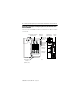
ControlLogix Data Highway Plus-Remote I/O Communication Interface Module Prepare the Chassis for Module Installation Before you install the DHRIO module, you must install and connect a ControlLogix chassis and power supply. Power Supply Chassis 43234 For information on installing these products, refer to the publications listed below.
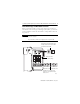
ControlLogix Data Highway Plus-Remote I/O Communication Interface Module 9 Determine Module Slot Location The figure below shows chassis slot numbering in a 4-slot chassis. Slot 0 is the first slot and is always the leftmost slot in the rack (the first slot to the right of the power supply). You can use any size ControlLogix chassis and install the module in any slot. You can also install multiple 1756-DHRIO modules in the same chassis.
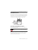
ControlLogix Data Highway Plus-Remote I/O Communication Interface Module Install the Module ATTENTION Do not force the module into the backplane connector. If you cannot seat the module with firm pressure, check the alignment. Forcing the module into the chassis can damage the backplane connector or the module. 1. Align the circuit board with top and bottom guides in the chassis. 2. Slide the module into the chassis. Make sure the module backplane connector properly connects to the chassis backplane.
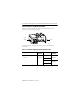
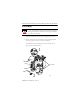
ControlLogix Data Highway Plus-Remote I/O Communication Interface Module 11 Remove or Replace the Module (When Applicable) 1. Push on upper and lower module tabs to disengage them. 2. Slide the module out of the chassis. 1 POWER POWER 2 43237 If you are replacing an existing module with an identical one, and you want to resume identical system operation, you must install the new module in the same slot.
ControlLogix Data Highway Plus-Remote I/O Communication Interface Module Wire the Connectors for the Module Channels Wiring Label 8-pin mini DIN programming terminal connection parallel to channel A when channel A is configured for DH+ communication.
ControlLogix Data Highway Plus-Remote I/O Communication Interface Module 13 Connect the Programming Terminal and DH+ or Remote I/O Network 1. Connect the programming terminal to the 8-pin mini DIN connector. 2. Connect the DH+ or Remote I/O network to the channel A or B connector as appropriate.
ControlLogix Data Highway Plus-Remote I/O Communication Interface Module Check Power Supply and Module Status Alphanumeric status indicator illuminates and cycles through a sequence of messages (described on page 15). H+/RIO CHA CHB OK Module OK status indicator is solid red, then flashing green. Power Supply indicator is green. 43241 At powerup the module’s alphanumeric display begins a cycle through the following sequences.
ControlLogix Data Highway Plus-Remote I/O Communication Interface Module 15 Troubleshoot the Power Supply If the alphanumeric indicator on the 1756-DHRIO module does not cycle through these messages on powerup, refer to the following table and to the Troubleshooting section that follows. If the POWER indicator is Power Supply Status is Recommended Action Off Not operating. Turn power switch ON. Check power wiring connections. Check fuse. On Operating. None, normal operation.
ControlLogix Data Highway Plus-Remote I/O Communication Interface Module Code Description Recommended Action CNFG FALT Incorrect DH+ routing table configuration. Correct the configuration. Refer to the 1756-DHRIO User Manual, publication 1756-UM0514. Incorrect Data Highway object configuration. Verify the module is inserted in correct slot. Data Highway Plus OK Normal operation for that channel. None. LINK Channel B is disabled because Channel A is used for 230k DH+ operation.
ControlLogix Data Highway Plus-Remote I/O Communication Interface Module 17 Interpret the Status Indicators The three status indicators on the module provide information about your module and the status of each channel. The following tables outline the indicator condition and the corresponding status, and explain what each condition means. If the Module OK indicator is Module Status Off Not operating. Recommended Action 1.Apply chassis power. 2.
ControlLogix Data Highway Plus-Remote I/O Communication Interface Module If the channel A or B indicator is in this channel mode then the channel status is take this action Off All Not on line. Place channel on line. Green RIO scanner Active RIO link. All adapter modules are present and not faulted. None, normal operation. DH+ Operating. None, normal operation. RIO scanner One or more nodes faulted or failed. Check power at other racks. DH+ No other node on the network. Check cables.
ControlLogix Data Highway Plus-Remote I/O Communication Interface Module 19 Specifications ControlLogix Data Highway Plus-Remote I/O Communication Interface Module - 1756-DHRIO Attribute Value Cat. No. 1756-DHRIO Module Location 1756 ControlLogix chassis Backplane Current (mA) at 24V 1.7 mA Backplane Current (mA) at 5V 850 mA Power Dissipation, Max. 4.5 W Thermal Dissipation, Max. 15.4 BTU/hr Baud Rate 57.6 Kbaud 115.2 Kbaud 230.
ControlLogix Data Highway Plus-Remote I/O Communication Interface Module Environmental Specifications Attribute Value Operating Temperature IEC 60068-2-1 (Test Ad, Operating Cold), IEC 60068-2-2 (Test Bd, Operating Dry Heat), IEC 60068-2-14 (Test Nb, Operating Thermal Shock): 0…60 °C (32…140 °F) Non-Operating Temperature IEC 60068-2-1 (Test Ab, Unpackaged Non-operating Cold), IEC 60068-2-2 (Test Bb, Unpackaged Non-operating Dry Heat), IEC 60068-2-14 (Test Na, Unpackaged Non-operating Thermal Shock)
ControlLogix Data Highway Plus-Remote I/O Communication Interface Module 21 Environmental Specifications Attribute Value Radiated RF Immunity IEC 61000-4-3: 10V/m with 1 kHz sine-wave 80% AM from 80…2000 MHz 10V/m with 200 Hz 50% Pulse 100% AM at 900 MHz 10V/m with 200 Hz 50% Pulse 100% AM at 1890 MHz 3V/m with 1 kHz sine-wave 80% AM from 2000…2700 MHz EFT/B Immunity IEC 61000-4-4: ±4 kV at 5 kHz on communications ports Surge Transient Immunity IEC 61000-4-5: ±2 kV line-earth(CM) on communications po
ControlLogix Data Highway Plus-Remote I/O Communication Interface Module Certifications Certifications(1) (when product is marked) UL c-UL-us c-UL-us CSA CSA CE C-Tick EEx (1) UL Listed Industrial Control Equipment. See UL File E65584. UL Listed Industrial Control Equipment, certified for US and Canada. See UL File E65584. UL Listed for Class I, Division 2 Group A,B,C,D Hazardous Locations, certified for U.S. and Canada. See UL File E194810. CSA Certified Process Control Equipment.
ControlLogix Data Highway Plus-Remote I/O Communication Interface Module 23 Additional Resources These documents contain additional information concerning related Rockwell Automation products. Resource Description ControlLogix Data Highway Plus-Remote I/O Communication Interface Module user manual, publication 1756-UM514 Provides information about configuring, operating and troubleshooting the 1756-DHRIO module. Industrial Automation Wiring and Grounding Guidelines, publication 1770-4.
Rockwell Automation Support Rockwell Automation provides technical information on the Web to assist you in using its products. At http://support.rockwellautomation.com, you can find technical manuals, a knowledge base of FAQs, technical and application notes, sample code and links to software service packs, and a MySupport feature that you can customize to make the best use of these tools.