
User Manual
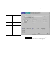

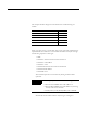
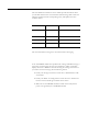
Table Of Contents
- 1756-UM532A-EN-P
- Important User Information
- Table of Contents
- Purpose of This Manual
- Preface
- 1756-DH485 Module Overview
- Overview of the DH-485 Network
- Introduction
- DH-485 Network Description
- DH-485 Network Protocol
- DH-485 Token Rotation
- DH-485 Network Initialization
- Devices that Use the DH-485 Network
- 1747-AIC Isolated Link Coupler for DH-485
- 1761-NET-AIC Advanced Interface Converter Product Overview
- Operating Modes
- Device Compatibility
- Misconception about the 1761-NET-AIC Converter
- 1747-UIC USB to DH-485 Interface Converter
- Example System Configuration
- Important Planning Considerations
- Additional Resources
- Use Data Highway 485 Network
- Use RSLinx Software to Create a Routing Table
- Communicate from an SLC 5/03 Controller to a Logix Controller over a DH-485 Network
- Communicate Between SLC Controllers over DH+ and DH485 Networks
- Communicate Between a PLC-5 Controller and a Remote SLC 5/03 Controller over Multiple DH-485 Networks
- Communicate from an SLC 5/05 Controller to an SLC 5/03 Controller over an EtherNet/IP Network
- Communicate to a SLC 5/03 Controller on a DH-485 Network
- Communicate from a Logix Controller to an SLC 5/03 Controller over EtherNet/IP and DH-485 Networks
- Specifications
- Troubleshoot the 1756-DH485 Module
- Index
- How Are We Doing?
- Rockwell Automation Support
- Backcover
1 Publication 1756-UM532A-EN-P - May 2006
Appendix
B
Troubleshoot the 1756-DH485 Module
Introduction
This chapter describes diagnostics and methods of troubleshooting the
module.
Check Power Supply and
Module Status
When you apply power to the module, three events take place simultaneously.
Alphanumeric status indicator on the module illuminates and cycles through
the following sequence of messages:
– INIT
– Channel A and the network used for channel A
– Channel A node address
– Channel A status
– Channel B and the network used for channel B
– Channel B node address
– Channel B status
This channel sequences run continuously during normal module
operation.
Module OK status indicator flashes red, then goes solid green.
For See
Check Power Supply and Module Status B-1
Interpret the LED Status Indicators B-2
Interpret the Alphanumeric Indicators B-3
Interpret the OK Status Indicator B-4
Routing Errors in DH-485 Messaging B-4
EXAMPLE
For example, if your module uses the following:
• Channel A for DH485 with node address 14
• Channel B for DH485 with node address 0, but being
the only node on the network.
• A DH, A#14, A OK, B DH, B#0, ONLY NODE