
User Manual


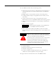
Table Of Contents
- 1756-UM532A-EN-P
- Important User Information
- Table of Contents
- Purpose of This Manual
- Preface
- 1756-DH485 Module Overview
- Overview of the DH-485 Network
- Introduction
- DH-485 Network Description
- DH-485 Network Protocol
- DH-485 Token Rotation
- DH-485 Network Initialization
- Devices that Use the DH-485 Network
- 1747-AIC Isolated Link Coupler for DH-485
- 1761-NET-AIC Advanced Interface Converter Product Overview
- Operating Modes
- Device Compatibility
- Misconception about the 1761-NET-AIC Converter
- 1747-UIC USB to DH-485 Interface Converter
- Example System Configuration
- Important Planning Considerations
- Additional Resources
- Use Data Highway 485 Network
- Use RSLinx Software to Create a Routing Table
- Communicate from an SLC 5/03 Controller to a Logix Controller over a DH-485 Network
- Communicate Between SLC Controllers over DH+ and DH485 Networks
- Communicate Between a PLC-5 Controller and a Remote SLC 5/03 Controller over Multiple DH-485 Networks
- Communicate from an SLC 5/05 Controller to an SLC 5/03 Controller over an EtherNet/IP Network
- Communicate to a SLC 5/03 Controller on a DH-485 Network
- Communicate from a Logix Controller to an SLC 5/03 Controller over EtherNet/IP and DH-485 Networks
- Specifications
- Troubleshoot the 1756-DH485 Module
- Index
- How Are We Doing?
- Rockwell Automation Support
- Backcover
Publication 1756-UM532A-EN-P - May 2006
1-2 1756-DH485 Module Overview
Module Features
The 1756-DH-485 module offers the following features:
• Sends messages between devices on DH-485 networks and devices on
other networks such as ControlNet, EtherNet/IP, or other DH-485
networks
• Bridges support to other NetLinx networks via the CLX gateway
• Configure channels and ports using RSLinx Classic software, version
2.43 or later
• Accesses other networks by using a routing table editor that lets
DH-485 devices use the 1756-DH485 module and ControlLogix chassis
• Supports all benefits and attributes of a ControlLogix communication
module
• Supports firmware upgrades
• Removal and insertion under power (RIUP), can be removed and
inserted under power without disrupting power to other modules in the
chassis
• 4-character display
• Default Controller Slot feature for local messaging
• Serial Port Configuration
• No limit on number of modules per chassis, up to the number of
available slots and the capabilities of the power supply
This figure shows the external features of the 1756-DH485 module.
TIP
Download firmware upgrades via the backplane. Do
not use DH485 network for downloads.
WARNING
!
When you insert or remove the module while backplane
power is on, an electrical arc can occur. This could cause an
explosion in hazardous location installations.
Be sure that power is removed or the area is nonhazardous
before proceeding. Repeated electrical arcing causes
excessive wear to contacts on both the module and its
mating connector. Worn contacts may create electrical
resistance that can affect module operation.