ControlLogix DH-485 Communication Module 1756-DH485 User Manual
Important User Information Solid state equipment has operational characteristics differing from those of electromechanical equipment. Safety Guidelines for the Application, Installation and Maintenance of Solid State Controls (publication SGI-1.1 available from your local Rockwell Automation sales office or online at http://literature.rockwellautomation.com) describes some important differences between solid state equipment and hard-wired electromechanical devices.
Table of Contents Important User Information . . . . . . . . . . . . . . . . . . . . . . . . . . . . . . . . 1-2 Preface Purpose of This Manual. . . . . . . . . . . . . . . . . . . . . . . . . . . . . . . Preface-i Who Should Use This Manual. . . . . . . . . . . . . . . . . . . . . . . . . . Preface-i Other Resources. . . . . . . . . . . . . . . . . . . . . . . . . . . . . . . . . . . . . Preface-i Chapter 1 1756-DH485 Module Overview Introduction . . . . . . . . . . . . . . . . . . . . . . . . . . . .
Table of Contents ii Chapter 3 Use Data Highway 485 Network Introduction . . . . . . . . . . . . . . . . . . . . . . . . . . . . . . . . . . . . . . . . . . . . . 3-1 What Is Data Highway 485? . . . . . . . . . . . . . . . . . . . . . . . . . . . . . . . . 3-1 Link Design . . . . . . . . . . . . . . . . . . . . . . . . . . . . . . . . . . . . . . . . . . 3-2 Two Methods of Communication Over a DH-485 Network . . . . . . 3-2 Use DH-485 Messaging . . . . . . . . . . . . . . . . . . . . . . . . . . . . . .
Table of Contents iii Chapter 6 Communicate Between SLC Controllers over DH+ and DH485 Networks Introduction . . . . . . . . . . . . . . . . . . . . . . . . . . . . . . . . . . . . . . . . . . . . . 6-1 SLC 5/04 Controller Sends a Remote Message . . . . . . . . . . . . . . . . . 6-2 Hardware Configuration . . . . . . . . . . . . . . . . . . . . . . . . . . . . . . . . 6-2 Create the Routing Table in RSLinx Software . . . . . . . . . . . . . . . 6-3 Configure the SLC 5/03 Controller Channel 1 Link ID . .
Table of Contents iv Chapter 10 Communicate from a Logix Controller to an SLC 5/03 Controller over EtherNet/IP and DH-485 Networks Introduction . . . . . . . . . . . . . . . . . . . . . . . . . . . . . . . . . . . . . . . . . . . . Hardware Configuration . . . . . . . . . . . . . . . . . . . . . . . . . . . . . . . . . . Create a Remote 1756-ENBT Message in RSLogix 5000 . . . . . . . . Configure the Message. . . . . . . . . . . . . . . . . . . . . . . . . . . . . . . . . . . .
Preface Purpose of This Manual This manual describes how to understand, configure, and troubleshoot your ControlLogix Data Highway 485 communication interface module. This manual also provides step-by-step procedures on how to use the 1756-DH485 module to send DH-485 messages between ControlLogix, PLC, and SLC controllers in DH-485 applications. Who Should Use This Manual Use this manual if you program applications that use 1756-DH485 modules.
Preface ii Notes: Publication 1756-UM532A-EN-P - May 2006
Chapter 1 1756-DH485 Module Overview Introduction What the Module Does This chapter describes the 1756-DH485 module, and what you must know and do before you begin to use it.
1-2 1756-DH485 Module Overview Module Features The 1756-DH-485 module offers the following features: • Sends messages between devices on DH-485 networks and devices on other networks such as ControlNet, EtherNet/IP, or other DH-485 networks • Bridges support to other NetLinx networks via the CLX gateway • Configure channels and ports using RSLinx Classic software, version 2.
1756-DH485 Module Overview 1-3 External Features of the 1756-DH485 Module Alphanumeric Status Indicator Backplane Connector Door Label Channel and Module Status Indicators Channel A Connector Channel B Connector 43842 Prevent Electrostatic Discharge The DH-485 module is sensitive to electrostatic discharge. ATTENTION ! This equipment is sensitive to electrostatic discharge, which can cause internal damage and affect normal operation.
1-4 1756-DH485 Module Overview Removal and Insertion Under Power You can install or remove the module while chassis power is applied if you observe the following precautions. WARNING ! Publication 1756-UM532A-EN-P - May 2006 When you insert or remove the module while backplane power is on, an electrical arc can occur. This could cause an explosion in hazardous location installations. Be sure that power is removed or the area is nonhazardous before proceeding.
1756-DH485 Module Overview 1-5 The first example is a typical gateway application connecting multiple networks together. Typical Applications In this example you can: • upload and download SLC 500 and Panelview display programs. • seamlessly communicate between SLC controllers. • connect multiple DH-485 networks together for inter-network communications, for example, messages between SLC 5/03 controllers.
1-6 1756-DH485 Module Overview The second example shows how you can connect or migrate a legacy system to a new installation with RSLogix software. • Connect multiple DH-485 networks together for inter-network communications. • Message between SLC 5/03 controllers. • Provide connection to other NetLinx networks. • Access through a single point and download to an SLC controller, MicroLogix controller, and Panelview display.
1756-DH485 Module Overview Remote Messaging 1-7 The configuration of remote messaging is similar to data highway remote I/O (DHRIO). It is achieved through routing table functions and module configuration. The multi-hop functionality is available in RSLogix 5 and 500 (version 6.
1-8 1756-DH485 Module Overview The 1756-DH485 module can route a message through up to four communications networks and three chassis. This limit applies only to the routing of a message and not to the total number of networks or chassis in a system. Routing Limitations DH-485 and CIP Messaging The 1756-DH485 module lets devices, such as ControlLogix, PLC, and SLC controllers exchange information.
56-DH485 Module Overview 1-9 Alphanumeric Indicators When you apply power to the module, the alphanumeric display begins to cycle through the following sequence. 1. All LEDs flash on then off -CHA, CHB OK 2. OK displays red then changes to green. 3. INIT displays. 4. Firmware Revision flashes on scrolling display: DH-485 5. Channel A and the network used for channel A. 6. Channel A node address. 7. Channel A status. 8. Channel B and the network used for channel. 9. Channel B node address. 10.
1-10 1756-DH485 Module Overview Notes: Publication 1756-UM532A-EN-P - May 2006
Chapter 2 Overview of the DH-485 Network Introduction DH-485 Network Description The information in this chapter will help you plan, install, and operate devices on a DH-485 network. This chapter also contains information that describes the DH-485 network functions, network architecture, and performance characteristics.
2-2 Overview of the DH-485 Network The protocol used to control message transfers on the DH-485 network supports two classes of devices: initiators and responders. All initiators on the network get a chance to initiate message transfers. To determine which initiator has the right to transmit, a token passing algorithm is used.
Overview of the DH-485 Network Devices that Use the DH-485 Network 2-3 Presently, the following SLC 500 devices support the DH-485 network: Devices that Use the DH-485 Network Catalog Number Description Installation Requirement Function Publication 1756-DH485 ControlLogix DH485 Communication Module ControlLogix Chassis Bridge DH485 messages in ControlLogix. 1756-UM532 1747-Lxxx SLC 500 Programmable Controllers SLC Chassis Programmable controllers.
2-4 Overview of the DH-485 Network Devices that Use the DH-485 Network Catalog Number Description Installation Requirement Function Publication 2707-L8P1(1), 2707-L8P2(1), 2707-L40P1(1), 2707-L40P2(1), 2707-V40P1(1), 2707-V40P2(1), 2707-V40P2N(1), 2707-M232P3(1), and 2707-M485P3(1) DTAM Plus and DTAM Micro Operator Interfaces(1) Panel Mount Provides electronic operator interface for SLC 500 controllers.
Overview of the DH-485 Network 2-5 You can also use the isolated link coupler to provide connectivity between devices for distances greater than 1.8 m (6 ft) up to a maximum of 1219 m (4000 ft). Below is an example of a remote connection between a computer running your programming software and an SLC 500 controller. Remote Connection Between a Computer Running Programming Software and an SLC 500 Controller RSLogix 500 Software 1747-UIC UIC 1747-C13 1747-AIC 1747-AIC >1.
2-6 Overview of the DH-485 Network 1761-NET-AIC Advanced Interface Converter Product Overview The AIC+ advanced interface converter provides a communication link between various networks devices. Ports 1, 2, and 3 are used for making the communication connections. The AIC+ is compatible with a variety of SLC and MicroLogix controllers and the 1756-DH485 communications module. The MicroLogix controllers provide power to the AIC+ via port 2’s cable.
Overview of the DH-485 Network 2-7 Node Address Identification There is no node address associated with the network port (Port 3). Port 1 Node Address (The node address is configured in the device connected to Port 1.) Misconception about the 1761-NET-AIC Converter Port 2 Node Address (The node address is configured in the device connected to Port 2.) Use this write-on area to mark the node address of each connection. The function of the 1761-NET-AIC converter is to accomplish two tasks.
2-8 Overview of the DH-485 Network Below is an example of a DH-485 network. Example System Configuration Example DH-485 Network System Configuration Personal Computer Personal Computer SLC 5/03, 5/04, or 5/05 Modular Controller SLC 500 20-Point Fixed Controller with 2-Slot Expansion Chassis 1747-UIC Interface Converter 1761-NET-AIC Advanced Interface Converter 1747-AIC Isolated Link Coupler DH-485 Network max.
Overview of the DH-485 Network 2-9 Configure the SLC 5/03, SLC 5/04, and SLC 5/05 Controller Channel 0 for DH-485 The RS-232 port (channel 0) of the SLC 5/03, SLC 5/04, and SLC 5/05 controllers can be configured for DH-485 protocol. You can connect channel 0 of the SLC 5/03, SLC 5/04, and SLC 5/05 controllers to a DH-485 network using the 1747-CP3 cable and a 1761-NET-AIC Advanced Interface Converter (AIC+). In this case, the AIC+ must be powered with 24V dc.
2-10 Overview of the DH-485 Network Important Planning Considerations Carefully plan your network configuration before installing any hardware.
Overview of the DH-485 Network 2-11 Plan Cable Routes Follow these guidelines to help protect the communication cable from electrical interference: • Keep the communication cable at least 1.52 m (5 ft) from any electric motors, transformers, rectifiers, generators, arc welders, induction furnaces, or sources of microwave radiation. • If you must run the cable across power feed lines, run the cable at right angles to the lines.
2-12 Overview of the DH-485 Network Software Considerations Software considerations include the configuration of the network and the parameters that can be set to the specific requirements of the network.
Overview of the DH-485 Network 2-13 Maximum Node Address Setting The maximum node address parameter should be set as low as possible. This minimizes the amount of time used in soliciting successors when initializing the network. If all nodes are addressed in sequence from 0, and the maximum node address is equal to the address of the highest addressed node, the token rotation will improve by the amount of time required to transmit a solicit successor packet plus the slot timeout value.
2-14 Overview of the DH-485 Network Notes: Publication 1756-UM532A-EN-P - May 2006
Chapter 3 Use Data Highway 485 Network Introduction What Is Data Highway 485? This chapter describes the basics of the Data Highway 485 system and the operation of a DH-485 network.
3-2 Use Data Highway 485 Network Link Design When you design your DH-485 link, you should use good design practices, including laying out the link before installation. We also recommend you consider the following when designing your DH-485 link: • All performance requirements • Maintenance • Possible future changes to the link Use a Belden 9842 or a Belden 3106A cable to connect your module to DH-485. Only connect a DH-485 network using a daisy-chain configuration.
Use Data Highway 485 Network Use DH-485 Messaging 3-3 DH-485 Messaging offers the following benefits: • You can send messages between devices on the same link. • You can send messages between devices on different links. DH-485 messaging is divided into two types: • Local DH-485 Messaging - See page 3-3 • Remote DH-485 Messaging - See page 3-5 Before you can design a control system to meet your application needs, be aware of the difference between Local DH-485 Messaging and Remote DH-485 Messaging.
3-4 Use Data Highway 485 Network This figure shows an SLC controller sending a local message to Channel A on the 1756-DH485 module. Because the controller slot for Channel A is configured to 0, the message is forwarded to the ControlLogix controller in slot 0.
Use Data Highway 485 Network 3-5 Limitations of Local DH-485 Messaging When using Local DH-485 Messaging, you must remember: • the DH-485 message contains only a node ID for a node on the DH-485 network. • a local DH-485 message sent to the node ID of a port on the 1756-DH485 module is forwarded to a single user-configured controller slot. • messages on one DH-485 network cannot be routed to other networks.
3-6 Use Data Highway 485 Network This figure shows an example of remote DH-485 messaging between SLC/03 (or later) controller A and SLC 5/03 (or later) controller B.
Use Data Highway 485 Network 3-7 The message originates on the source network. The destination network is the message’s target network. This applies to all source and destination networks, including DH-485, ControlNet, EtherNet/IP, and a ControlLogix chassis backplane. IMPORTANT For remote DH-485 messaging, the ControlLogix chassis backplane should be considered a separate, independent network. Therefore, a system of 1 DH-485 network and one ControlLogix chassis is a two-link system.
3-8 Use Data Highway 485 Network Programming Message Block Instructions in a Controller for Remote DH-485 Messaging Before programming your message block instructions in your controller, you must: • determine which links will send and receive remote DH-485 messaging. • draw a network to make sure you meet the design requirements for remote DH-485 messaging. If you are using remote DH-485 messaging, you must also: • assign link numbers. The numbers must be a decimal value between 1-199.
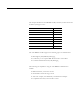
Use Data Highway 485 Network 3-9 The following table lists what the controllers are capable of on DH-485.
3-10 Use Data Highway 485 Network Limitations of Remote DH-485 Messaging Remote DH-485 messages are encapsulated in CIP messages and sent on CIP connections when they are sent across ControlNet, EtherNet/IP, and the ControlLogix chassis backplane. Although this is transparent to the user, there are resource limits associated with CIP on the 1756-DH485 module. The 1756-DH485 module supports up to 32 CIP connections.
Use Data Highway 485 Network Configuration Information in DH-485 Messaging 3-11 When you are doing DH-485 messaging, you must first set up the 1756-DH485 module configuration. The following configuration information is stored in the non-volatile (NVS) memory on your 1756-DH485 module when you configure the module using RSLinx software. • Any routing table that may be needed to send DH-485 messages through the module.
3-12 Use Data Highway 485 Network When an error occurs while sending a message to a remote link, it appears to the sending station as an application timeout because error messages are not routed back. When an error occurs during routing, it may be dropped.
Use Data Highway 485 Network 3-13 The Example of DH-485 Routing Configuration figure below shows an example DH-485 routing configuration. All node numbers on DH-485 are given in decimal. Node numbers on ControlNet and slot numbers in ControlLogix chassis are given in decimal. Links IDs for all networks are given in decimal. Example DH-485 Network Routing Configuration IMPORTANT Some devices in this figure have the same node number because they are on different networks.
3-14 Use Data Highway 485 Network Use the Common Industrial Protocol (CIP) Messaging Common Industrial Protocol (CIP) is the communication mechanism on ControlLogix chassis, ControlNet, and EtherNet/IP networks with the Encapsulation Protocol (EPIC) protocol. Like DH-485 messaging, CIP supports communication between devices on the same link and physically separate links. However, CIP messaging uses a different method to route messages than DH-485 messaging.
Chapter 4 Use RSLinx Software to Create a Routing Table Introduction Choose the Correct Software This chapter describes how to configure your 1756-DH485 module in DH-485 applications. For more information on the configuration software, refer to the online help in each. For See Choose the Correct Software 4-1 Use RSLinx Software to Create a Routing Table 4-2 Create the Routing Table 4-3 The programming software you need is dependent on what products you are using with the 1756-DH485 module.
4-2 Use RSLinx Software to Create a Routing Table Use RSLinx Software to Create a Routing Table DH-485 protocols do not use the Common Industrial Protocol (CIP), the communication protocol used in the ControlLogix architecture. The 1756-DH485 module is the transition point from the DH-485 network to ControlLogix. In this capacity, the 1756-DH485 module serves as the DH-485 message source and requires a full message route, or path, to deliver the message.
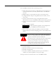
Use RSLinx Software to Create a Routing Table Create the Routing Table 4-3 To create a routing table for your application, follow these steps: 1. Start RSLinx. 2. Browse the network. 3. Right-click on the 1756-DH485 module. 4. Use the left-side navigation bar to see your DH-485 application, as shown in the example below. A.Expand the configuration tree until the module appears. B. Right-click on the 1756-DH485 module. C. Select Module Configuration.
4-4 Use RSLinx Software to Create a Routing Table 5. Select the DH-485 Routing Table tab. You must build the routing table based on the 1756-DH485 modules in the ControlLogix chassis. Each link ID (for example: chassis backplane, channels A and B of any 1756-DH485 module in the chassis) is initially undefined.
Use RSLinx Software to Create a Routing Table 4-5 6. You must assign link IDs, as shown below. A.Right-click on the 1756-DH485 module. B.Click Edit Module. C. Assign Link IDs and click OK. IMPORTANT Keep track of your Link ID assignments. You need the Link ID values when you send messages via RSLogix 500 and RSLogix 5000 software.
4-6 Use RSLinx Software to Create a Routing Table The 1756-DH485 routing table displays with the link IDs defined.
Use RSLinx Software to Create a Routing Table 4-7 7. Assign a Link ID for the chassis backplane. A.Right-click on the Backplane. B.Click Edit Module. C. Assign Link IDs and click OK. 8. Click OK The software prompts you to download routing table changes. 9. Click Yes. This completes the routing table creation process.
4-8 Use RSLinx Software to Create a Routing Table Set the Controller Slot Setting the controller slot location creates a simple way for the SLC controllers to exchange data with the ControlLogix controller as long as the SLC controller is on the same DH-485 network as the module. The SLC controller can use local messaging to send data to a ControlLogix controller with this feature. No routing table is required.
Chapter 5 Communicate from an SLC 5/03 Controller to a Logix Controller over a DH-485 Network Introduction This chapter describes how to set up the communications initiated by an SLC 5/03 controller through a 1756-DH485 module to a 1756-Lx controller.
5-2 Communicate from an SLC 5/03 Controller to a Logix Controller over a DH-485 Network Hardware Configuration In this hardware configuration, the communications are initiated by an SLC 5/03 controller. The message is sent to a 1756-DH485 module and the 1756-Lx controller is located in slot 11. Communications Between an SLC 5/03 Controller and a 1756-DH485 Module 1756--L1 Controller 1756-DH485 DH485 DH+/RIO AIC+ CO M B A TERM DH485 network communicating through link couplers.
Communicate from an SLC 5/03 Controller to a Logix Controller over a DH-485 Network Use the Controller Slot to Route the Local Message 5-3 When a local DH485 message is received, the message will automatically be routed to the controller based on the configured slot number. In this case, the 1756-Lx controller is in slot 11. A routing table is not needed. Enter the slot number of the controller.
5-4 Communicate from an SLC 5/03 Controller to a Logix Controller over a DH-485 Network Create a Local Message in RSLogix 500 Publication 1756-UM532A-EN-P - May 2006 This is an example of a local message being initiated by the SLC 5/03 controller.
Communicate from an SLC 5/03 Controller to a Logix Controller over a DH-485 Network Configure the Message 5-5 This is the Setup dialog for the example message.
5-6 Communicate from an SLC 5/03 Controller to a Logix Controller over a DH-485 Network Create a Logic Map for the Local Message in RSLogix 5000 Software Publication 1756-UM532A-EN-P - May 2006 You must logically map the SLC data address to the ControlLogix tag. To get to the Logix Map in RSLogix 5000 software go to: Logic > Map PLC/SLC Messages. This is the logic map needed for the example message.
Chapter 6 Communicate Between SLC Controllers over DH+ and DH485 Networks Introduction This chapter describes how to set up the message communications between two SLC controllers.
6-2 Communicate Between SLC Controllers over DH+ and DH485 Networks SLC 5/04 Controller Sends a Remote Message In this example an SLC 5/04 controller initiates a remote message and sends it to an SLC 5/03 Controller. Hardware Configuration In this hardware configuration, an SLC 5/04 controller sends a remote message to an SLC 5/03 controller. • The SLC 5/04 controller is on a DH+ network (1). • The SLC 5/04 controller connects to Channel B on the 1756-DHRIO module (2).
Communicate Between SLC Controllers over DH+ and DH485 Networks 6-3 Create the Routing Table in RSLinx Software These are the routing tables needed for the example configuration. This is the routing table for the 1756-DH485 module. In this example, the: • SLC 5/04 controller is on the DH+ network. • SLC 5/04 controller is node 10 octal. • SLC 5/04 controller connects to a 1756-DHRIO module at node 56 octal or 46 decimal. • connection is on Channel B of the 1756-DHRIO.
6-4 Communicate Between SLC Controllers over DH+ and DH485 Networks Configure the SLC 5/03 Controller Channel 1 Link ID The SLC 5/03 remote link ID needs to be programmed to match the link IDs configured into the 1756-DH485 module. These are labeled in the channel configuration as the Channel 1 Passthru Link ID.
Communicate Between SLC Controllers over DH+ and DH485 Networks 6-5 Configure the SLC 5/04 Channel 1 Link ID The SLC 5/04 controller remote link ID needs to be programmed to match the link IDs configured into the 1756-DH485 module. These are labeled in the channel configuration as the Channel 1 Passthru Link ID.
6-6 Communicate Between SLC Controllers over DH+ and DH485 Networks Create a Message in RSLogix 500 This is the message for the example configuration.
Communicate Between SLC Controllers over DH+ and DH485 Networks 6-7 Configure the Message This is the Setup dialog for the example message. The SLC 5/04 controller connects to a 1756-DHRIO module at node 56 octal or 46 decimal. The SLC 5/04 controller sends a remote message to the SLC 5/03 controller that is on a DH485 network. The SLC 5/03 controller is located at node 1. The DH485 network is assigned as link 1.
6-8 Communicate Between SLC Controllers over DH+ and DH485 Networks SLC 5/03 Controller Sends a Remote Message In this example an SLC 5/03 controller initiates a remote message and sends it to an SLC 5/04 controller. Hardware Configuration In this hardware configuration, an SLC 5/03 controller initiates a message to an SLC 5/04 controller on a DH-485 network. (1) • This SLC 5/03 controller connects to Channel A on the 1756-DH485 module.
Communicate Between SLC Controllers over DH+ and DH485 Networks 6-9 Create the Routing Table in RSLinx Software These are the routing tables needed for the example configuration. In this example, the: • SLC 5/03 controller is connected to Channel A of the 1756-DH485 module. The 1756-DH485 node address on the DH-485 network is node 0. • 1756-DHRIO and the 1756-DH485 modules are on the same backplane. • 1756-DH485 module is in slot 14. • 1756-DHRIO module is in slot 8.
6-10 Communicate Between SLC Controllers over DH+ and DH485 Networks Create a Remote Message in RSLogix 500 This is the example message for the hardware configuration. Click on Setup Screen to configure the message.
Communicate Between SLC Controllers over DH+ and DH485 Networks 6-11 Configure the Message This is the Setup Screen for the example message. In this example, the SLC 5/03 controller is connected to Channel A of the 1756-DH485 module. The 1756-DH485 node address on the DH-485 network is node 0.
6-12 Communicate Between SLC Controllers over DH+ and DH485 Networks Notes: Publication 1756-UM532A-EN-P - May 2006
Chapter 7 Communicate Between a PLC-5 Controller and a Remote SLC 5/03 Controller over Multiple DH-485 Networks Introduction This chapter describes how to set up the communications for a remote PLC-5 controller to send a message to a remote SLC 5/03 controller over multiple DH-485 Networks. For See Hardware Configuration 7-4 Create a Message in RSLogix 5 7-4 Configure the Message 7-5 Create the Routing Table 7-3 IMPORTANT 1 The examples use SLC 5/03 modules to send DH-485 messages.
7-2 Communicate Between a PLC-5 Controller and a Remote SLC 5/03 Controller over Multiple DH-485 Networks Hardware Configuration In this hardware configuration, a remote PLC-5 controller sends a message to an SLC 5/03 controller. Communications Between a PLC-5 and a Remote SLC 5/03 Controller on a DH-485 Network ControlLogix Controller 1756-DH485 1756-DHRIO DH485 DH+/RIO Channel A (2), DH+ Network Channel A (4) (3) The 1756-DHRIO and the 1756-DH485 are on the same backplane.
Communicate Between a PLC-5 Controller and a Remote SLC 5/03 Controller over Multiple DH-485 Networks Create the Routing Table 7-3 These are the routing tables for the message in the example configuration. This is the routing table for the 1756-DH485 module. This is the routing table for the 1756-DHIRO module.
7-4 Communicate Between a PLC-5 Controller and a Remote SLC 5/03 Controller over Multiple DH-485 Networks Configure the PLC-5 DH+ Channel 1A Link ID The PLC-5 DH+ Channel 1A Link ID needs to be configured. This is an example of the channel properties. Create a Message in RSLogix 5 Publication 1756-UM532A-EN-P - May 2006 This is an example of a remote message for the example configuration.
Communicate Between a PLC-5 Controller and a Remote SLC 5/03 Controller over Multiple DH-485 Networks Configure the Message 7-5 This is the Setup dialog for the message in the example configuration.
7-6 Communicate Between a PLC-5 Controller and a Remote SLC 5/03 Controller over Multiple DH-485 Networks Notes: Publication 1756-UM532A-EN-P - May 2006
Chapter 8 Communicate from an SLC 5/05 Controller to an SLC 5/03 Controller over an EtherNet/IP Network Introduction This chapter describes the communications from an SLC 5/05 controller to an SLC 5/03 controller over an EtherNet/IP network. For See Hardware Configuration 8-2 Create a Message in RSLogix 500 8-3 Configure the Message 8-4 Review the Multihop Feature in RSLogix 500 8-5 IMPORTANT 1 The examples use SLC 5/05 controllers to send DH-485 messages.
8-2 Communicate from an SLC 5/05 Controller to an SLC 5/03 Controller over an EtherNet/IP Network Hardware Configuration In this hardware configuration, an SLC 5/05 controller communicates to an SLC 5/03 controller over an EtherNet/IP network. • The SLC 5/05 controller initiates a message. (1) • The message is sent over an EtherNet/IP network to a 1756-ENBT module. (2) • The message is then sent over the backplane to a 1756-DH485 module.
Communicate from an SLC 5/05 Controller to an SLC 5/03 Controller over an EtherNet/IP Network Create a Message in RSLogix 500 8-3 This is the message for the example configuration. Click on Setup Screen to configure the message. Click on Setup Screen to configure the message.
8-4 Communicate from an SLC 5/05 Controller to an SLC 5/03 Controller over an EtherNet/IP Network Configure the Message This is the setup screen for the example configuration. In this example, the: • The SLC 5/05 controller on an EtherNet/IP network with it’s IP address at 100.100.100.8. • The SLC 5/05 controller sends the message to an SLC 5/03 controller on a DH-485 network via the 1756-ENBT module at IP address 100.100.100.7 over the backplane to a 1756-DH485 module.
Communicate from an SLC 5/05 Controller to an SLC 5/03 Controller over an EtherNet/IP Network Review the Multihop Feature in RSLogix 500 8-5 The multihop feature of RSLogix 500 takes care of routing this remote message. No routing table is required. This is the multihop dialog for the example configuration.
8-6 Communicate from an SLC 5/05 Controller to an SLC 5/03 Controller over an EtherNet/IP Network Notes: Publication 1756-UM532A-EN-P - May 2006
Chapter 9 Communicate to a SLC 5/03 Controller on a DH-485 Network Introduction This chapter describes how to configure remote CIP communication from a 1756-L55 controller to an SLC 5/03 controller through DH+ and DH485 networks. For See Hardware Configuration 9-2 Create a Message in RSLogix 5000 9-3 Configure the Message 9-4 IMPORTANT 1 The examples use the 1756-DH485 module to initiate the message to the SLC 5/03 module.
9-2 Communicate to a SLC 5/03 Controller on a DH-485 Network In this hardware configuration, the ControlLogix controller initiates a CIP message from the 1756-DHRIO module to an SLC 5/03 controller located on a DH-485 network.
Communicate to a SLC 5/03 Controller on a DH-485 Network Create a Message in RSLogix 5000 9-3 This is the message for the example configuration. Click to configure the message.
9-4 Communicate to a SLC 5/03 Controller on a DH-485 Network Configure the Message These are the configuration dialogs for the example message. Data table memory is in the SLC 5/03 controller. The message is coming from the ControlLogix controller. Destination storage is in the 1756-L55 controller. Path Item Description dhrio_ser_B When you browse to the local 1756-DHRIO module appears if you have it configured in the I/O configuration tree in RSLogix 5000 software.
Chapter 10 Communicate from a Logix Controller to an SLC 5/03 Controller over EtherNet/IP and DH-485 Networks Introduction This chapter describes how to set up communication from a Logix controller to an SLC controller over an EtherNet/IP network. For See Hardware Configuration 10-2 Create a Remote 1756-ENBT Message in RSLogix 5000 10-3 Configure the Message 10-4 IMPORTANT 1 The examples use SLC 5/03 modules to send DH-485 messages.
10-2 Communicate from a Logix Controller to an SLC 5/03 Controller over EtherNet/IP and DH-485 Networks Hardware Configuration In this hardware configuration, a Logix controller communicates to an SLC 5/03 controller over EtherNet/IP. • The 1756-ENBT module (1) to communicate to a remote 1756-ENBT module (2) over the EtherNet/IP network backplane • The 1756-DH485 module (3) then communicates through Channel A to the SLC 5/03 (4) controller through link couplers over a DH-485 Network.
Communicate from a Logix Controller to an SLC 5/03 Controller over EtherNet/IP and DH-485 Networks Create a Remote 1756-ENBT Message in RSLogix 5000 10-3 This is an example remote 1756-ENBT message. Click the button to configure the message. Configure the message.
10-4 Communicate from a Logix Controller to an SLC 5/03 Controller over EtherNet/IP and DH-485 Networks Configure the Message Message Type: SLC Typed Write Source Element: interger_slc_dh485[20] Make sure you specify the starting array element, for example [20]. Number of Elements: 1 Destination Element: N7:20 Publication 1756-UM532A-EN-P - May 2006 This dialog shows example values on the Configuration tab for the remote message.
Communicate from a Logix Controller to an SLC 5/03 Controller over EtherNet/IP and DH-485 Networks 10-5 This is the Communication tab for the remote message. Path Item Description series_A This means go to the backplane to slot 5 where the 1756-ENBT named Series_A is located. Series A is defined as backplane 1, slot 5. 2 EtherNet/IP port. 100.100.100.7 The remote 1756-ENBT. 1 Go to the backplane of the remote 1756 chassis. 14 Go to the slot location of the 1756-DH485 module.
10-6 Communicate from a Logix Controller to an SLC 5/03 Controller over EtherNet/IP and DH-485 Networks Notes: Publication 1756-UM532A-EN-P - May 2006
Appendix A Specifications ControlLogix DH-485 Communications Module 1756-DH485 Attribute Value Module Location ControlLogix chassis Maximum Backplane Current Load 850 mA @ +5.1V dc and 1.7mA @ 24V dc from I/O chassis backplane Power Dissipation 4.5 W Thermal Dissipation, Max 15.4 BTU/hr Isolation Voltage 50V Tested to withstand 750V dc for 60 s Available Communication Rates (1) Wiring Category (1) 19.
A-2 Specifications Environmental Specifications Attribute Value EFT/B Immunity IEC 61000-4-4: +/-2 kV at 5 kHz on communications ports Surge Transient Immunity IEC 61000-4-5: +/-1 kV line-earth (CM) on communications ports Conducted RF Immunity IEC 61000-4-6: 10 Vrms with 1 kHz sine-wave 80%AM from 150 kHz...
Appendix B Troubleshoot the 1756-DH485 Module Introduction Check Power Supply and Module Status This chapter describes diagnostics and methods of troubleshooting the module. For See Check Power Supply and Module Status B-1 Interpret the LED Status Indicators B-2 Interpret the Alphanumeric Indicators B-3 Interpret the OK Status Indicator B-4 Routing Errors in DH-485 Messaging B-4 When you apply power to the module, three events take place simultaneously.
B-2 Troubleshoot the 1756-DH485 Module If the alphanumeric indicator on the 1756-DH485 module does not cycle through these messages when you apply power, refer to the following table and to the troubleshooting section that follows. Power Cycle Indicators Interpret the LED Status Indicators If the POWER Indicator is Power Supply Status is Recommended Action Off Not operating. Turn power ON. Check power wiring connections. Check fuse. On Operating. None, normal operation.
Troubleshoot the 1756-DH485 Module Interpret the Alphanumeric Indicators B-3 Your 1756-DH485 module displays alphanumeric codes that provide diagnostic information about your module. The alphanumeric display flashes the codes at approximately one-second intervals. This table summarizes the codes. Alphanumeric Display Descriptions Message Description Recommended Action ONLY NODE Only node on DH-485 link. Check the cables. OFF LINE DH-485 link is in STOP Correct the configuration. state.
B-4 Troubleshoot the 1756-DH485 Module Interpret the OK Status Indicator The three LED status indicators on the module provide information about your module and the status of each channel. The following tables outline the indicator condition and the corresponding status, and explain what each condition means. Interpreting the OK Status Indicator If the Module OK Indicator is Module Status Recommended Action Off Not operating. Apply chassis power.
Troubleshoot the 1756-DH485 Module B-5 Routing Errors in Remote DH-485 Messaging If the 1756-DH485 module has a problem with routing a Remote DH-485 Message, it may return a response with an error status of D0 hex. An SLC controller displays this error as D000 hex when monitoring the message instruction. If you receive this error message, take the following actions: • Check your message instruction to make sure a valid local node destination, link ID and destination node were entered.
B-6 Troubleshoot the 1756-DH485 Module Notes: Publication 1756-UM532A-EN-P - May 2006
Index Numerics 1747-AIC link coupler using on the DH-485 network 2-4 1747-UIC description 2-7 example network 2-7 1756-DH485 module overview 1-1–1-9 module requirements 1-1 What does the module do? 1-1 1756-ENBT remote message 10-3, 10-5 1761-NET-AIC communication link 2-6 description 2-6 device compatibilty 2-6 operating modes 2-6 A AIC+ device compatibility 2-6 interface converter 2-7 node address identification 2-7 operating modes 2-6 overview 2-6 alphanumeric indicators 1-9, B-3 C D Data Highway 485
ii Index link coupler 1747-AIC 2-4 1761-NET-AIC 2-6 link design on a Data Highway 485 (DH-485) network 3-2 link IDs for remote Data Highway 485 (DH-485) messaging 3-6 local Data Highway 485 (DH-485) messaging 3-3 limitations 3-5 Receiving messages 3-4 routing errors B-4 M messaging Common Industrial Protocol (CIP) 3-14 Data Highway 485 (DH-485) 1-8 multiple networks connection of 1-5 routing errors in local Data Highway 485 (DH-485) messaging B-4 in remote Data Highway 485 (DH-485) messaging B-5 routing
Index software choose the correct software for DH485 applications 4-1 RSLinx 4-1 RSLogix 5 4-1 RSLogix 500 4-1 RSLogix 5000 4-1 Specifications 1756-DH485 module A-1 environmental conditions A-1 status indicators for use in troubleshooting B-4 system configuration, example 2-8 iii T troubleshoot B-1–B-5 power supply and module status B-1 use the alphanumeric indicators B-3 use the status indicators B-4 typical applications 1-5–1-6 U upload remote 1-7 Publication 1756-UM532A-EN-P - May 2006
iv Index Notes: Publication 1756-UM532A-EN-P - May 2006
How Are We Doing? Your comments on our technical publications will help us serve you better in the future. Thank you for taking the time to provide us feedback. You can complete this form and mail it back to us, visit us online at www.ab.com/manuals, or email us at RADocumentComments@ra.rockwell.com Pub. Title/Type ControlLogix DH-485 Communication Module Cat. No. 1756-DH485 Pub. No. 1756-UM532A-EN-P Pub. Date May 2006 Part No. 957988-29 Please complete the sections below.
PLEASE FASTEN HERE (DO NOT STAPLE) PLEASE FOLD HERE NO POSTAGE NECESSARY IF MAILED IN THE UNITED STATES BUSINESS REPLY MAIL FIRST-CLASS MAIL PERMIT NO.
Rockwell Automation Support Rockwell Automation provides technical information on the Web to assist you in using its products. At http://support.rockwellautomation.com, you can find technical manuals, a knowledge base of FAQs, technical and application notes, sample code and links to software service packs, and a MySupport feature that you can customize to make the best use of these tools.