Installation Instructions ControlLogix DH-485 Communications Module Catalog Number(s) 1756-DH485 Inside . . .
ControlLogix DH-485 Communications Module Important User Information Solid state equipment has operational characteristics differing from those of electromechanical equipment. Safety Guidelines for the Application, Installation and Maintenance of Solid State Controls (Publication SGI-1.1 available from your local Rockwell Automation sales office or online at http://www.literature.rockwellautomation.
ControlLogix DH-485 Communications Module 3 Environment and Enclosure ATTENTION This equipment is intended for use in a Pollution Degree 2 industrial environment, in overvoltage Category II applications (as defined in IEC publication 60664-1), at altitudes up to 2000 meters without derating. This equipment is considered Group 1, Class A industrial equipment according to IEC/CISPR Publication 11.
ControlLogix DH-485 Communications Module Prevent Electrostatic Discharge ATTENTION This equipment is sensitive to electrostatic discharge, which can cause internal damage and affect normal operation. Follow these guidelines when you handle this equipment: • • • • • • Touch a grounded object to discharge potential static. Wear an approved grounding wriststrap. Do not touch connectors or pins on component boards. Do not touch circuit components inside the equipment.
ControlLogix DH-485 Communications Module 5 Single-point Serial Communication Connections WARNING If you connect or disconnect the serial cable with power applied to this module or the serial device on the other end of the cable, an electrical arc can occur. This could cause an explosion in hazardous location installations. Be sure that power is removed or the area is nonhazardous before proceeding.
ControlLogix DH-485 Communications Module North American Hazardous Location Approval The following information applies when operating this equipment in hazardous locations: Informations sur l'utilisation de cet équipement en environnements dangereux: Products marked “CL I, DIV 2, GP A, B, C, D” are suitable for use in Class I Division 2 Groups A, B, C, D, Hazardous Locations and nonhazardous locations only.
ControlLogix DH-485 Communications Module 7 Informations sur l'utilisation de cet équipement en environnements dangereux: The following information applies when operating this equipment in hazardous locations: WARNING EXPLOSION HAZARD WARNING RISQUE D'EXPLOSION Do not disconnect equipment unless power has been removed or the area is known to be nonhazardous. Couper le courant ou s'assurer que l'environnement est classé non dangereux avant de débrancher l'équipement.
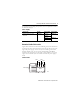
ControlLogix DH-485 Communications Module Identify Module Features Use this figure to identify module hardware components. Module Features Backplane Connector Alphanumeric Status Indicator Wiring Label Channel and Module Status Indicators Channel A Connector Channel B Connector 43842 Prepare the Chassis for Module Installation Before you install the 1756-DH485 module, you must install and connect a ControlLogix chassis and power supply.
ControlLogix DH-485 Communications Module 9 For information on installing these products, refer to the publications listed in the table Power Supply. Power Supply Chassis Type Chassis Power Supply Power Supply Series B: 1756-A4, -A7, -A10, -A13, -A17 1756-IN080 1756-PA72 1756-IN078 1756-PB72 1756-PA75 1756-IN596 1756-PB75 Determine Module Slot Location Figure Slot Locations shows chassis slot numbering in a four-slot chassis.
ControlLogix DH-485 Communications Module Install or Remove the Module While Power Is Applied You can install or remove the module while chassis power is applied if you observe the following precautions. WARNING When you insert or remove the module while backplane power is on, an electrical arc can occur. This could cause an explosion in hazardous location installations. Be sure that power is removed or the area is nonhazardous before proceeding.
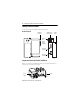
ControlLogix DH-485 Communications Module 11 Install the Module ATTENTION Do not force the module into the backplane connector. If you cannot seat the module with firm pressure, check the alignment. Forcing the module into the chassis can damage the backplane connector or the module. 1 Align the circuit board with top and bottom guides in the chassis. POWER Circuit board 2 Slide the module into the chassis. Make sure the module backplane connector properly connects to the chassis backplane.
ControlLogix DH-485 Communications Module Remove or Replace the Module (When Applicable) 1 Push on upper and lower module tabs to disengage them. POWER POWER Slide the module out of the chassis. 2 43237 If you are replacing an existing module with an identical one, and you want to resume identical system operation, you must install the new module in the same slot.
ControlLogix DH-485 Communications Module 13 Connect the 1756-DH485 Module to the 1761-NET-AIC Converter 1. Use the 1756-CP3 cable to connect each channel to a 1761-NET-AIC advanced interface convertor. 2. Connect the right-angle connector end of the cable to the 1761-NET-AIC converter. Right-angle connector end of 1756-CP3 cable 6 - DSR 7 - RTS 8 - CTS 9 - N/C 1 - DCD 2 - RXD 3 - TXD 4 - DTR 5 - GND 43843 3. Connect the straight connector end of the cable to the 1761-NET-AIC converter.
ControlLogix DH-485 Communications Module Connect the 1761-NET-AIC Converter to the DH-485 Network Use the RS-485 connector to connect the 1761-NET-AIC converter to the DH-485 network. For more information on how to use the 1761-NET-AIC convertor, see the following publications: • Advanced Interface Converter (AIC+) and DeviceNet Interface (DNI) Installation Instructions, publication 1761-IN002 • Advanced Interface Converter (AIC+) User Manual, publication 1761-6.
ControlLogix DH-485 Communications Module 15 Check Power Supply and Module Status Alphanumeric status indicator illuminates and cycles through a sequence of messages (described in the Alphanumeric Display Descriptions table). Power Supply indicator is green. Module OK status indicator is solid red, then flashing green. 43846 At powerup the module’s alphanumeric display begins a cycle through the following sequences.
ControlLogix DH-485 Communications Module Troubleshoot the Power Supply If the alphanumeric indicator on the 1756-DH485 module does not cycle through these messages when you turn the power on, refer to the Power Supply Status table and to the Troubleshooting section that follows. Power Supply Status POWER Indicator Power Supply Status Off Not operating. Recommended Action Turn power switch ON. Check power wiring connections. Check fuse. On Operating. None, normal operation.
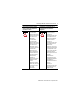
ControlLogix DH-485 Communications Module 17 Alphanumeric Display Descriptions Code Description Recommended Action OK Normal operation for that channel. None. LINK ??? None OFF Interpret the LED Status Indicators The LED status indicators on the module provide information about your module and the status of each channel. The following tables outline the indicator condition and the corresponding status, and explain what each condition means.
ControlLogix DH-485 Communications Module LED Actions Channel A or B Indicator Channel Status Recommended Action Off Not online. Place channel online. Solid Green Operating. None, normal operation. Flashing Green No other node on the network. Check cables. Solid Red Hardware fault. Reboot module. If red reoccurs, replace module. Flashing Red Either: • Faulted adapters detected. • Duplicate node detected • Check cables. Check power at other racks. • Check node address.
ControlLogix DH-485 Communications Module 19 Specifications ControlLogix DH-485 Communications Module - 1756-DH485 Specifications Specification Value Module Location ControlLogix chassis Maximum Backplane Current Load 850 mA @ +5.1V dc and 1.7mA @ 24V dc from I/O chassis backplane Power Dissipation, Max 4.5 W Thermal Dissipation, Max 15.4 BTU/hr Isolation Voltage 50V Tested to withstand 750V dc for 60 s Available Communication Rates 19.2 Kbps (default) and 9600 Kbps Screw Terminal Torque 0.
ControlLogix DH-485 Communications Module Environmental Specifications Specification Operational Temperature Value IEC 60068-2-1 (Test Ad, Operating Cold), IEC 60068-2-2 (Test Bd, Operating Dry Heat), IEC 60068-2-14 (Test Nb, Operating Thermal Shock): 0...60 °C (32...140 °F) Storage Temperature IEC 60068-2-1 (Test Ab, Un-packaged Non-operating Cold), IEC 60068-2-2 (Test Bb, Un-packaged Non-operating Dry Heat), IEC 60068-2-14 (Test Na, Un-packaged Non-operating Thermal Shock): -40...85 °C (-40...
ControlLogix DH-485 Communications Module 21 Environmental Specifications Specification Value Surge Transient Immunity IEC 61000-4-5: Conducted RF Immunity IEC 61000-4-6: Magnetic Field Immunity IEC 61000-4-8: Enclosure Type Rating None (open-style) +/-1 kV line-earth (CM) on communications ports 10 Vrms with 1 kHz sine-wave 80%AM from 150 kHz...
ControlLogix DH-485 Communications Module Additional Resources This product also has a user manual, publication 1756-UM532. To view it, visit http://www.rockwellautomation.com/literature To purchase a manual, you can: • Contact your distributor or Rockwell Automation representative • Call 800.963.9548 (USA/Canada) or 001.320.725.1574 (outside USA/Canada) ControlLogix, DH+, DH-485, RSLogix 5000, and RSLinx are trademarks of Rockwell Automation, Inc.
ControlLogix DH-485 Communications Module 23 Notes: Publication 1756-IN587A-EN-P - September 2005
Rockwell Automation Support Rockwell Automation provides technical information on the web to assist you in using its products. At http://support.rockwellautomation.com, you can find technical manuals, a knowledge base of FAQs, technical and application notes, sample code and links to software service packs, and a MySupport feature that you can customize to make the best use of these tools.