Installation Instructions ControlLogix ControlNet Bridge (Catalog Numbers 1756-CNB, -CNBR) Series C and D Use this document as a guide to install the ControlLogix ControlNet Bridge module.
Important User Information Because of the variety of uses for the products described in this publication, those responsible for the application and use of this control equipment must satisfy themselves that all necessary steps have been taken to assure that each application and use meets all performance and safety requirements, including any applicable laws, regulations, codes and standards. The illustrations, charts, and layout examples shown in this guide are intended solely for purposes of example.
Throughout this manual we use the following notes to make you aware of safety considerations: WARNING ! ATTENTION ! Identifies information about practices or circumstances that have the potential to create an explosion hazard. Identifies information about other practices or circumstances that can lead to personal injury or death, property damage or economic loss.
Understanding Compliance to European Union Directive If this product bears the CE marking, it is approved for installation within the European Union and EEA regions. It has been designed and tested to meet the following directives.
Enclosure and Environmental Requirements Specific To This Product This product must be mounted within a suitable system enclosure to prevent personal injury resulting from accessibility to live parts. The interior of this enclosure must be accessible only by the use of a tool. This industrial control equipment is intended to operate in a Pollution Degree 2 environment, in overvoltage category II applications, (as defined in IEC publication 664A) at altitudes up to 2000 meters without derating.
Understanding Standalone and Redundant Control You can use both the 1756-CNB and 1756-CNBR modules either standalone or in a redundant control chassis pair. For standalone control, only one set of modules is required. For redundant control, two ControlLogix chassis are populated with identical pairs of modules called partners. The chassis that performs active control is called the primary chassis and the modules in the chassis are called primary modules.
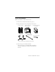
Prepare to Install the Module Before you install the module make sure you: 1. Know how to handle the module (see page 5) 2. Have all of the necessary components shown below: 1756-CNB or 1756-CNBR 1786-TPR, -TPS -TPYR, or -TPYS(1) (1) 1756-A4, 1756-A7, 1756-A10, 1756-A13, or 1756-A17 1786-TP (temporary network connections) 1756-PA72/75 or 1756-PB72/75 power supply small screwdriver (optional) 1786-TPS or 1786-TPYS taps recommended for network connections. 3.
All 1756-CNB and 1756-CNBR modules are keeper-capable, as listed in the following table. CNB(R) Series Major/Minor Revision Keeper Type A 1.xx Single-Keeper B 2.xx Multi-Keeper C 3.xx Single-Keeper C 4.xx Multi-Keeper D 5.xx Multi-Keeper You must match the keeper to the type of network, or upgrade the firmware of the module at MAC ID 01 to be multi-keeper capable. Refer to the ControlLogix ControlNet Interface Module User Manual, publication 1756-6.5.3, for more information.
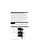
Identify Module Features Refer to the following figure to identify the hardware components of the 1756-CNB and CNBR modules.
Set the Module’s Network Address Switches Use your fingers or a small screwdriver to set the module’s network address switches. For modules in a standalone chassis, you must specify a unique ControlNet network address; for modules in a redundant chassis, you must specify the same address for the secondary module that you specified for the corresponding primary module. You can select an address of 01 to 99 for modules in a standalone chassis or 01 to 98 for modules in redundant chassis.
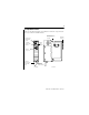
Prepare the Chassis for Module Installation Before you install the CNB module, you must install and connect a ControlLogix chassis and power supply. A 4-slot chassis with a power supply is shown below. Power Supply Chassis For information on installing these products, refer to the publications listed in the following table. Chassis Type Series B: 1756-A4, -A7, -A10, -A13 Chassis Installation Power Supply Power Supply Installation Pub. No. 1756-IN080 1756-PA72/B Pub. No. 1756-5.
Determine Module Slot Location The figure below shows chassis slot numbering in a 4-slot chassis. Slot 0 is the first slot and is always the leftmost slot in the rack (the first slot to the right of the power supply). You can use any size ControlLogix chassis and install the module in any slot. You can also install multiple 1756-CNB/R modules in the same chassis. You can install as many modules as your power supply can accommodate (i.e., number for which the power supply is rated).
Installing or Removing the Module Under Power You can install or remove the module while chassis power is applied if you observe the following precautions. WARNING ! When you insert or remove a module while backplane power is on, an electrical arc may occur. An electrical arc can cause personal injury or property damage by: • sending an erroneous signal to your system's actuators causing unintended machine motion or loss of process control. • causing an explosion in a hazardous environment.
Install the Module Align the circuit board with top and bottom guides in the chassis. Circuit board Slide the module into the chassis. Make sure the module backplane connector properly connects to the chassis backplane. ATTENTION ! The module is properly installed when it is flush with the power supply or other installed modules. Do not force the module into the backplane connector. If you cannot seat the module with firm pressure, check the alignment.
Removing or Replacing the Module (if needed) Upper tab Push on the upper and lower tabs to disengage them. Then slide the module out of the chassis. If you are replacing an existing module with an identical one, and you want to resume identical system operation, you must install the new module with the same ControlNet address in the same slot.
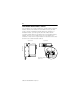
The following figure shows an example ControlNet network using redundant media. 1756-CNBR (in 1756-A4 chassis) ControlNet node ControlNet link redundant media (optional) ControlNet node When connecting the 1756-CNB/R module to a ControlNet network, you should also refer to the following documentation: • ControlNet Coax Tap Installation Instructions, publication 1786-5.7 • ControlNet Cable System Planning and Installation Manual, publication 1786-6.2.
Connecting to the Network Using a Tap Perform the following steps to connect the module to the network using a tap. 1. Remove and save the dust cap(s) from the ControlNet tap(s). ATTENTION ! Segment 1 Do not allow any metal portions of the tap to contact any conductive material. If you disconnect the tap from the module, place the dust cap back on the straight or right angle connector to prevent the connector from accidentally contacting a metallic grounded surface.
IMPORTANT To prevent inadvertent reversal of the tap connections (resulting in incorrect status displays requiring troubleshooting), check the tap drop cable for the label indicating the attached segment before making your connection. To work properly, when you use modules in a redundant control chassis pair, the primary and redundant partner modules must be connected to the same network segment. If you are using redundant media, connect the channel of each partner to the same network segment.
3. Apply power to the module and check module status. Use the following flowchart as a guide. Turn the chassis power supply on. Module status indicator red? See the troubleshooting table on page 23. No Yes Module performs a power-on self-test initialization. INIT Module status indicator red? Modules are in a redundant control chassis pair. WAIT RM OR No Initialization is complete. The status indicator blinks green.
Connecting a Programming Terminal to the Network Using 1786-CP Cable To connect a programming terminal to the network using a 1786-CP cable, you have the following options: 1. using a 1784-KTC, -KTCx, or -PCC communication card and a 1786-CP cable: 1756-CNBR 1784-KTC, KTCx, PCIC, or PCC card 1786-CP Cable ControlNet link IMPORTANT To work properly, the primary and redundant partner module must be connected to the same network segment.
The 1786-CP cable can be plugged into any ControlNet product’s NAP to provide programming capability on the ControlNet network. A programming terminal connected through this cable is counted as a node and must have a unique network address. ATTENTION ! Use a 1786-CP cable when connecting a programming terminal to the network through NAPs. Using a commercially available RJ-style cable could result in network failure.
Troubleshooting The 1756-CNB and 1756-CNBR modules have the diagnostic indicators shown below: 1756-CNB 1756-CNBR Module Status Display - see pages 23 to 26. Module Status Indicator see pages 23 to 26. ControlNet Channel Status Indicators - see page 26.
Module Status Indicator and Display The Module Status Indicator LED and Module Status Display provide diagnostic information as summarized in the following table. Diagnostics LED Display Cause OK Off Red Action 1. Check the power supply. 2. Check the cable connectors. 3. Make sure the module is firmly seated in the chassis. 4. If the indicator remains off, replace the module. Module’s network address is set 1. (Optional, see page 11.) Msg Turn chassis power supply off.
Diagnostics LED Display Cause OK Red DUPL NODE RACK ERR STOP WAIT RM Flashing BOOT Red ROM UPDT SNGL KPR! Action For a redundant system this may 1. (For redundant systems only.) be a temporary condition during Wait 10 seconds; if the chassis switchover. Otherwise, condition persists, perform the the module’s network address is following steps: the same as another module’s on 2. (Optional, see page 11.) the link. Turn chassis power supply off. 3. Remove the module from the chassis. 4.
Diagnostics LED Display Cause Action OK INIT BW >MAX Normal operation Module is initializing. Module is receiving too much network traffic and connections are timing out. The network bandwidth has been exceeded. None required CMPT Secondary CNB is compatible with its partner. Secondary CNB is disqualified with no partner. OK Green DSNP PwDS PwQg PwQS PwNS Qfng QS SW ERR Flashing CNFG Green ERR NET ERR None require (temporary condition).
Diagnostics LED Display OK Green or SO_1 Off SO_2 SO_3 SN_1 SN_2 SN_3 ?Cpt !Cpt (1) Cause Action Old primary switchover phase 1 in progress. Old primary switchover phase 2 in progress. Old primary switchover phase 3 in progress. New primary switchover phase 1 in progress. New primary switchover phase 2 in progress. New primary switchover phase 3 in progress. CNB has not determined if it is compatible. CNB has determined that it is not compatible.
The following table summarizes the meanings of these states: A and Cause Action No power Faulted unit None or power up. Cycle power or reset unit If fault persists, contact A-B representative or distributor. None B Off Steady red Alternating Self-test red/green Alternating red/off Incorrect node configuration Check network address and other ControlNet configuration parameters.
Hazardous Location information The following information applies when operating this equipment in hazardous locations: Products marked “CL I, DIV 2, GP A, B, C, D” are suitable for use in Class I Division 2 Groups A, B, C, D, Hazardous Locations and nonhazardous locations only. Each product is supplied with markings on the rating nameplate indicating the hazardous location temperature code.
Informations sur l’utilisation de cet équipement en environnements dangereux : Les produits marqués « CL I, DIV 2, GP A, B, C, D » ne conviennent qu’à une utilisation en environnements de Classe I Division 2 Groupes A, B, C, D dangereux et non dangereux. Chaque produit est livré avec des marquages sur sa plaque d’identification qui indiquent le code de température pour les environnements dangereux.
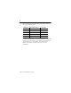
Module Specifications 1756-CNB 1756-CNBR • 1 BNC connector for • 2 BNC connectors non-redundant media for redundant operation media operation • 1 NAP (RJ-45 8-pin • 1 NAP (RJ-45 with shield) 8-pin with shield) cable quad shield RG-6 coaxial cable ground isolation transformer Electrical power dissipation 5.14 W thermal dissipation 17.5 BTU/hr backplane current 970 mA @ 5.1 V 1.0 A @ 5.1 V 1.7 mA @ 24 V 1.
ControlLogix is a trademark of Rockwell Automation. ControlNet is a trademark of ControlNet International, Ltd.
Publication 1756-IN571B-EN-P - April 2001 Supersedes Publications 1756-5.32 - December 1999 and 1756-5.71 - July 1998 PN 957536-76 © 2001 Rockwell International Corporation.