Installation Instructions ControlLogix ControlNet Interface Module Catalog Numbers 1756-CNB, 1756-CNBR, Series E Contents For See Page Important User Information 2 European Hazardous Location Approval 3 North American Hazardous Location Approval 4 Environment and Enclosure 5 Prevent Electrostatic Discharge 6 About the 1756-CNB and 1756-CNBR Series E Modules 6 Understand Standalone and Redundant Control 7 Before You Begin 8 Install or Remove the Module Under Power 14 Install the Module
ControlLogix ControlNet Interface Module Important User Information Solid state equipment has operational characteristics differing from those of electromechanical equipment. Safety Guidelines for the Application, Installation and Maintenance of Solid State Controls (Publication SGI-1.1 available from your local Rockwell Automation sales office or online at http://literature.rockwellautomation.
ControlLogix ControlNet Interface Module 3 European Hazardous Location Approval European Zone 2 Certification (The following applies when the product bears the EEx Marking.) This equipment is intended for use in potentially explosive atmospheres as defined by European Union Directive 94/9/EC.
ControlLogix ControlNet Interface Module North American Hazardous Location Approval The following information applies when operating this equipment in hazardous locations: Informations sur l'utilisation de cet équipement en environnements dangereux: Products marked “CL I, DIV 2, GP A, B, C, D” are suitable for use in Class I Division 2 Groups A, B, C, D, Hazardous Locations and nonhazardous locations only.
ControlLogix ControlNet Interface Module 5 Environment and Enclosure ATTENTION This equipment is intended for use in a Pollution Degree 2 industrial environment, in overvoltage Category II applications (as defined in IEC publication 60664-1), at altitudes up to 2000 meters without derating. This equipment is considered Group 1, Class A industrial equipment according to IEC/CISPR Publication 11.
ControlLogix ControlNet Interface Module Prevent Electrostatic Discharge ATTENTION This equipment is sensitive to electrostatic discharge, which can cause internal damage and affect normal operation. Follow these guidelines when you handle this equipment: • • • • • • Touch a grounded object to discharge potential static. Wear an approved grounding wriststrap. Do not touch connectors or pins on component boards. Do not touch circuit components inside the equipment.
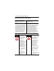
ControlLogix ControlNet Interface Module 7 Understand Standalone and Redundant Control You can use the 1756-CNB and 1756-CNBR Series E modules as standalone or in firmware version 11.xx as redundant control. For standalone control, only one set of modules is required. For redundant control, two ControlLogix chassis are populated with identical pairs of modules called partners. The chassis that performs active control is called the primary chassis and the modules in the chassis are called primary modules.
ControlLogix ControlNet Interface Module Before You Begin Before you install the module you need to make sure you: • Know how to handle the module. Refer to the section Prevent Electrostatic Discharge.
ControlLogix ControlNet Interface Module 9 All 1756-CNB and 1756-CNBR modules are keeper-capable, as listed. 1756-CNB and 1756-CNBR Major/Minor Revision Keeper Type A 1.xx Single-keeper B 2.xx Multi-keeper C 3.xx Single-keeper C 4.xx Multi-keeper D 5.xx Multi-keeper D 7.xx Multi-keeper E 10.xx Multi-keeper E 11.xx Multi-keeper You must match the keeper to the type of network, or upgrade the firmware of the module at MAC ID 01 to be multi-keeper capable.
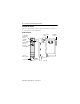
ControlLogix ControlNet Interface Module Identify Module Features Refer to the figure Module Features to identify the hardware components of the 1756-CNB and 1756-CNBR modules.
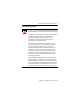
ControlLogix ControlNet Interface Module 11 Set the Module’s Network Address Switches Use your fingers or a small screwdriver to set the module’s network address switches. For modules in a standalone chassis, you must specify a unique ControlNet network address; for modules in a redundant chassis, you must specify the same address for the secondary module that you specified for the corresponding primary module. Top of Module Front of Module Side of Module This module’s network address is 23.
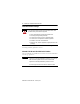
ControlLogix ControlNet Interface Module Prepare the Chassis for Module Installation Before you install the module, you must install and connect a ControlLogix chassis and power supply. A 4-slot chassis with a power supply is shown in the figure Chassis and Power Supply. Chassis and Power Supply Power Supply Chassis For information on installing these products, refer to the table Chassis Installation Publications.
ControlLogix ControlNet Interface Module 13 Determine Module Slot Location The figure Chassis Slot Numbering shows chassis slot numbering in a 4-slot chassis. Slot 0 is the first slot and is always the leftmost slot in the rack (the first slot to the right of the power supply). You can use any size ControlLogix chassis and install the module in any slot. You can also install multiple 1756-CNB and 1756-CNBR modules in the same chassis.
ControlLogix ControlNet Interface Module Install or Remove the Module Under Power You can install or remove the module while chassis power is applied if you observe the following precautions. WARNING When you insert or remove the module while backplane power is on, an electrical arc can occur. This could cause an explosion in hazardous location installations. Be sure that power is removed or the area is nonhazardous before proceeding.
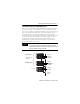
ControlLogix ControlNet Interface Module 15 Install the Module Align the circuit board with top and bottom guides in the chassis. Slide the module into the chassis. Make sure the module backplane connector properly connects to the chassis backplane Circuit Board The module is properly installed when it is flush with the power supply or other installed modules. ATTENTION Do not force the module into the backplane connector. If you cannot seat the module with firm pressure, check the alignment.
ControlLogix ControlNet Interface Module Remove the Module Upper Tab Push on the upper and lower tabs to disengage them. Then slide the module out of the chassis. If you are replacing an existing module with an identical one, and you want to resume identical system operation, you must install the new module with the same ControlNet address in the same slot.
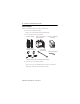
ControlLogix ControlNet Interface Module 17 Connect the Module to the Network You can connect the module to the ControlNet network using a tap (1786-TPR, 1786-TPS, 1786-TPYR, or 1786-TPYS) or a network access cable (1786-CP). WARNING TIP If you connect or disconnect the communications cable with power applied to this module or any device on the network, an electrical arc can occur. This could cause an explosion in hazardous location installations.
ControlLogix ControlNet Interface Module When connecting the module to a ControlNet network, you should also refer to the following documentation: • ControlNet Coax Tap Installation Instructions, publication 1786-5.7 • ControlNet Cable System Planning and Installation Manual, publication CNET-IN002 TIP For network connections we recommend taps with a straight connector (1786-TPS or 1786-TPYS) because of the location of the BNC connectors on the bottom of the module.
ControlLogix ControlNet Interface Module 19 Connect to the Network with a Tap Perform the following steps to connect the module to the network using a tap. 1. Remove and save the dust caps from the ControlNet network taps. ATTENTION Do not allow any metal portions of the tap to contact any conductive material. If you disconnect the tap from the module, place the dust cap back on the straight or right-angle connector to prevent the connector from accidentally contacting a metallic grounded surface.
ControlLogix ControlNet Interface Module IMPORTANT To prevent inadvertent reversal of the tap connections (resulting in incorrect status displays requiring troubleshooting), check the tap drop cable for the label indicating the attached segment before making your connection. To work properly, when you use modules in a redundant control chassis pair, the primary and redundant partner modules must be connected to the same network segment.
ControlLogix ControlNet Interface Module 21 3. Apply power to the module and check module status. Use the following flowchart as a guide. Turn the chassis power supply on. Module status indicator red? See the Troubleshoot section. No Yes Module performs a power-on self-test initialization. Modules are in a redundant control chassis pair. WAIT SRM OR INIT Module status indicator red? No Initialization is complete. The status indicator blinks green.
ControlLogix ControlNet Interface Module Connect a Programming Terminal to the Network with a 1786-CP Cable To connect a programming terminal to the network using a 1786-CP cable, you have the following options: • Use a 1784-KTC, 1784-KTCx, or 1784-PCC communication card and a 1786-CP cable: 1756-CNBR 1784-KTC, KTCx, PCIC, or PCC Card 1786-CP Cable ControlNet Link IMPORTANT To work properly, the primary and redundant partner module must be connected to the same network segment.
ControlLogix ControlNet Interface Module 23 The 1786-CP cable can be plugged into any ControlNet network product’s network access port (NAP) to provide programming capability on the ControlNet network. A programming terminal connected through this cable is counted as a node and must have a unique network address. ATTENTION Use a 1786-CP cable when connecting a programming terminal to the network through network access port (NAP).
ControlLogix ControlNet Interface Module Interpret the Module Status Indicator and Display The Module Status Indicator LED and Module Status Display table provide diagnostic information. Module Status Indicator LED and Module Status Display LED Display Cause OK Off None Red Msg scrolls(1) BPA# ERR BPRX ERR BPIC ERR The module is not communicating due to a power supply fault or internal fault. Action 1. Check the power supply. 2. Check the cable connectors. 3.
ControlLogix ControlNet Interface Module 25 Module Status Indicator LED and Module Status Display LED Display Cause OK Red DUPL NODE RACK ERR STOP WAIT SRM(2) Flashing BOOT Red ROM UPDT SNGL KPR! Action For a redundant system this may 1. (For redundant systems only.) Wait 10 seconds; if the be a temporary condition during condition persists, perform the chassis switchover. Otherwise, following steps: the module’s network address is 2. (Optional, see page 12.
ControlLogix ControlNet Interface Module Module Status Indicator LED and Module Status Display LED Display OK Green OK INIT BW >MAX CMPT(2) DSNP(2) PwDS(2) PwQg(2) PwQS(2) PwNS(2) Qfng(2) QS(2) SW ERR Cause Action Normal operation The module is initializing. The module is receiving too much network traffic and connections are timing out. The network bandwidth has been exceeded. The secondary module is compatible with its partner. The secondary module is disqualified with no partner.
ControlLogix ControlNet Interface Module 27 Module Status Indicator LED and Module Status Display LED Display OK Flashing CNFG Green ERR NET ERR Green or SO_1(2) Off SO_2(2) SO_3(2) SN_1(2) SN_2(2) SN_3(2) ?Cpt(2) !Cpt(2) (1) Cause Action ControlNet network configuration error. Network cabling error or no other active nodes on network. Recheck configuration. Re-check your network cabling and make sure another node on the network is active (online).
ControlLogix ControlNet Interface Module ControlNet Network Channel Status Indicators The ControlNet network channel status indicators appear in one of the following states: • Steady - indicator is on continuously in the defined state. • Alternating - the two indicators alternate between the two defined states at the same time (applies to both indicators viewed together). The two indicators are always in opposite states, out of phase.
ControlLogix ControlNet Interface Module 29 ControlNet Network Channel Status Indicators A and Cause Action Node is not configured to go on line Make sure the configuration manager node is present and working and selected address is B not greater than selected UMAX.(1) Flashing red/off Media fault No other nodes present on network Flashing red/green Incorrect network configuration Check media. For example: broken cables, loose connectors, missing terminators. Add other nodes to the network.
ControlLogix ControlNet Interface Module Specifications ControlLogix ControlNet Interface Module 1756-CNB, 1756-CNBR, Series E Attribute Value Connectors 1756-CNB 1756-CNBR 1 BNC connector for nonredundant media operation 1 NAP (RJ-45 8-pin with shield) 2 BNC connectors for redundant media operation 1 NAP (RJ-45 8-pin with shield) Cable Quad shield RG-6 coaxial cable Ground isolation Transformer ControlNet network communication rate 5M Diagnostics Yes Weight 1756-CNB 1756-CNBR 0.260 kg (0.
ControlLogix ControlNet Interface Module 31 ControlLogix ControlNet Interface Module 1756-CNB, 1756-CNBR, Series E Attribute Value Backplane current 970 mA @ 5.1 V 1.7 mA @ 24 V Isolation voltage (continuous-voltage withstand rating) 50V Tested to 500V ac for 60 seconds Wiring category(1) 2 - on communications ports (1) Use this Conductor Category information for planning conductor routing. Refer to Industrial Automation Wiring and Grounding Guidelines, publication 1770-4.1.
ControlLogix ControlNet Interface Module Environmental Specifications ControlLogix ControlNet Interface Module 1756-CNB, 1756-CNBR, Series E Attribute Value ESD immunity IEC 61000-4-2: 6 kV contact discharges 8 kV air discharges Radiated RF immunity Series E IEC 61000-4-3: 10 V/m with 1 kHz sine-wave 80%AM from 30…2000 MHz 10 V/m with 200 Hz 50% Pulse 100%AM at 900 MHz 10 V/m with 200 Hz 50% Pulse 100%AM at 1890 MHz 1 V/m with 1 kHz sine-wave 80%AM from 2000 MHz…2700 MHz EFT/B immunity IEC 61000-4
ControlLogix ControlNet Interface Module 33 Certifications 1756-CNB Series E and 1756-CNBR, Series E Certification Value Certifications UL UL Listed Industrial Control Equipment (when product is marked)(1) cULusUL Listed for Class I, Division 2 Group A,B,C,D Hazardous Locations, certified for U.S.
ControlLogix ControlNet Interface Module Additional Resources Publication Title Publication Number Industrial Automation Wiring and Grounding Guidelines 1770-4.1 ControlNet Modules in Logix5000 Control Systems CNET-UM001 ControlLogix Chassis Installation Instructions 1756-IN080 ControlLogix Power Supplies Installation Instructions 1756-IN078 ControlLogix Power Supplies Installation Instructions 1756-IN596 ControlNet Coax Tap Installation Instructions 1786-5.
ControlLogix ControlNet Interface Module 35 Notes: Publication 1756-IN604A-EN-P - February 2006
Rockwell Automation Support Rockwell Automation provides technical information on the web to assist you in using its products. At http://support.rockwellautomation.com, you can find technical manuals, a knowledge base of FAQs, technical and application notes, sample code and links to software service packs, and a MySupport feature that you can customize to make the best use of these tools.