Installation Instructions ControlLogix-XT ControlNet Interface Module Catalog Number 1756-CN2RXT Topic Page Important User Information 2 About the ControlLogix-XT ControlNet Module 6 About ControlLogix-XT Systems ControlLogix-XT with Traditional ControlLogix Components Using the 1756-CN2RXT for Standalone or Redundant Control Example Redundant ControlLogix-XT System 8 8 9 10 Before You Begin 10 Parts 11 Set the Module’s Network Address 11 Reset the Module to the Original Factory Settings 12
ControlLogix-XT ControlNet Interface Module Important User Information Solid state equipment has operational characteristics differing from those of electromechanical equipment. Safety Guidelines for the Application, Installation and Maintenance of Solid State Controls (Publication SGI-1.1 available from your local Rockwell Automation sales office or online at http://literature.rockwellautomation.
ControlLogix-XT ControlNet Interface Module 3 Environment and Enclosure ATTENTION This equipment is intended for use in a Pollution Degree 2 industrial environment, in overvoltage Category II applications (as defined in IEC 60664-1), at altitudes up to 2000 m (6562 ft) without derating. This equipment is considered Group 1, Class A industrial equipment according to IEC/CISPR 11.
ControlLogix-XT ControlNet Interface Module North American Hazardous Location Approval The following information applies when operating this equipment in hazardous locations: Informations sur l'utilisation de cet équipement en environnements dangereux: Products marked "CL I, DIV 2, GP A, B, C, D" are suitable for use in Class I Division 2 Groups A, B, C, D, Hazardous Locations and nonhazardous locations only.
ControlLogix-XT ControlNet Interface Module 5 European Hazardous Location Approval European Zone 2 Certification (The following applies when the product bears the Ex or EEx Marking) This equipment is intended for use in potentially explosive atmospheres as defined by European Union Directive 94/9/EC and has been found to comply with the Essential Health and Safety Requirements relating to the design and construction of Category 3 equipment intended for use in potentially explosive atmospheres, given in Ann
ControlLogix-XT ControlNet Interface Module Preventing Electrostatic Discharge ATTENTION This equipment is sensitive to electrostatic discharge, which can cause internal damage and affect normal operation. Follow these guidelines when you handle this equipment: • Touch a grounded object to discharge potential static. • Wear an approved grounding wriststrap. • Do not touch connectors or pins on component boards. • Do not touch circuit components inside the equipment.
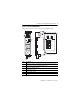
ControlLogix-XT ControlNet Interface Module 7 Features of the 1756-CN2RXT Module These are the hardware features of the 1756-CN2RXT module.
ControlLogix-XT ControlNet Interface Module About ControlLogix-XT Systems The ControlLogix-XT products include control and communication system components that, when used with FLEX I/O-XT products, provide a complete control system solution that can be used in environments where temperatures range from -20...70 °C (-4...158 °F). When used independently, the ControlLogix-XT system can withstand environments where the temperature ranges from -25...70 °C (-13...158 °F).
ControlLogix-XT ControlNet Interface Module 9 Using the 1756-CN2RXT for Standalone or Redundant Control You can use the 1756-CN2RXT modules either in standalone or redundant configurations. A standalone configuration uses: • one control chassis that contains the 1756-CN2RXT and the 1756-L63XT controller. • one or both channels of the 1756-CN2RXT module connected to the ControlNet network. A redundant configuration uses: • two controller chassis called the redundant chassis pair.
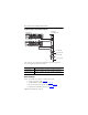
ControlLogix-XT ControlNet Interface Module Example Redundant ControlLogix-XT System Redundant ControlNet Media Primary Chassis Secondary Chassis To Remote I/O To Remote I/O To Remote I/O To Remote I/O This example of a redundant ControlLogix-XT system shows the chassis components listed in this table.
ControlLogix-XT ControlNet Interface Module 11 Parts To use your ControlNet module, you need these system components. 1756-A5XT or 1756-A7LXT X T X T X T X T 1756-PBXT X T - 1756-CN2RXT 1786-TPR, 1786-TPS, 1786-TPYR, or 1786-TPYS Set the Module’s Network Address Use a small screwdriver to set the module’s network address switches. For modules in a standalone chassis, you must specify a unique ControlNet network address. You can select an address of 01...99 for modules in a standalone chassis.
ControlLogix-XT ControlNet Interface Module Reset the Module to the Original Factory Settings If you need to reset the module to its original settings and clear all keeper information, complete the following steps. IMPORTANT The following procedure instructs you to remove power from the chassis before removing the module. This is only necessary if the module is in a Class I, Division 2 hazardous location. For more information, see Removal and Insertion Under Power (RIUP) on page 14. 1.
ControlLogix-XT ControlNet Interface Module 13 Prepare the Chassis for Module Installation Complete these tasks using the resources listed as references before you install your ControlNet module.
ControlLogix-XT ControlNet Interface Module Removal and Insertion Under Power (RIUP) WARNING When you insert or remove the module while backplane power is on, an electrical arc can occur. This could cause an explosion in hazardous location installations. Be sure that power is removed or the area is nonhazardous before proceeding. Repeated electrical arcing causes excessive wear to contacts on both the module and its mating connector.
ControlLogix-XT ControlNet Interface Module 15 3. Make sure the module backplane connector properly connects to the chassis backplane. ATTENTION Do not force the module into the backplane connector. If you cannot seat the module with firm pressure, check the alignment. Forcing the module into the chassis can damage the backplane connector or the module. The module is properly installed when it is flush with the power supply or other installed modules.
ControlLogix-XT ControlNet Interface Module Connect the Module to the Network WARNING If you connect or disconnect the communications cable with power applied to this module or any device on the network, an electrical arc can occur. This could cause an explosion in hazardous location installations. Be sure that power is removed or the area is nonhazardous before proceeding.
ControlLogix-XT ControlNet Interface Module 17 2. Attach the tap’s straight or right-angle connector to the appropriate BNC connector on the module. IMPORTANT Avoid accidentally reversing the tap connections. Before making your connection, check the tap drop cable for the label indicating the attached segment. Accidental connection reversals produce incorrect status displays and require troubleshooting.
ControlLogix-XT ControlNet Interface Module Apply Power and Check Status If not yet applied, apply power to the chassis power supply. Use this flowchart as a reference to determine module status after power is applied. Turn the chassis power supply on. Module status indicator red? No See Status Indicators on page 23. Yes Module performs a self-test initialization. TEST Module status indicator red? No Self-test is complete. The status indicator flashes green.
ControlLogix-XT ControlNet Interface Module 19 Remove the Module To remove the module, perform this procedure. 1. Push on the upper and lower tabs to disengage them. 2. Slide the module out of the chassis. X T IMPORTANT X T If you are removing and replacing an existing module with an identical one, and you want to resume identical system operation, you must install the new module with the same ControlNet address in the same slot.
ControlLogix-XT ControlNet Interface Module Install the EDS File The EDS file can be uploaded directly from the module. This feature lets you register the EDS file for your module from within RSLinx software by following the steps listed below. 1. Open RSLinx software, version 2.55 or later, and browse for the module. 2. Right-click the module and select Upload EDS file from device. The Upload EDS wizard opens. 3. Complete the EDS wizard to register the EDS file.
ControlLogix-XT ControlNet Interface Module 21 Configure RSLinx Software to Use the USB Port The ControlNet interface module has a USB device port that uses a Type B receptacle. The port is USB 1.1-compatible and runs at 12 Mbps. To use the USB port of the 1756-CN2RXT, you must have RSLinx software, version 2.55 or later, installed on your workstation. Use a USB cable to connect your workstation to the USB port.
ControlLogix-XT ControlNet Interface Module Set Up the USB Driver To configure RSLinx software to use a USB port, first set up a USB driver by performing this procedure. 1. Connect your 1756-CN2RXT module to your workstation by installing a USB cable in your module’s USB port. The workstation monitor displays the Found New Hardware Wizard dialog box. 2. Click Install the software automatically (Recommended) and click Next. The software is installed. 3. Click Finish to set up your USB driver. 4.
ControlLogix-XT ControlNet Interface Module 23 Status Indicators The ControlLogix-XT ControlNet module has these status indicators. Module Status Display Channel Status Indicators Module Status Indicator Module Status Indicator and Display The Module Status indicator and Module Status display provide diagnostic information. Use this table to interpret the Module Status Indicator and Display.
ControlLogix-XT ControlNet Interface Module OK Display Indicator Red Reset CompleteChange Switch Settings FAIL Backplane Init(1) Stop Service Received Cause Recommended Action Module’s network address is set to 00, an invalid ControlNet address. 1. Remove power from the chassis. 2. Remove the module from the chassis. 3. Set the switches to their final value. See page page 11. 4. Replace the module in the chassis. 5. Apply power to the chassis. Replace the module.
ControlLogix-XT ControlNet Interface Module 25 Display OK Indicator Flashing Image red update Needed DUPLICATE NODE DETECTED Flash in progress TEST Cause Recommended Action Boot image running. Main firmware image needs to be updated. The module’s network address is the same as another module’s on the link. Update the module’s firmware by using the ControlFlash utility. 1. Remove power from the chassis. 2. Remove the module from the chassis. 3. Set the switches to their final value. See page 11. 4.
ControlLogix-XT ControlNet Interface Module Display OK Indicator Solid OK green INIT PASS CMPT(1) DSNP(1) PwDS(1) PQgS(1) PwQS(1) PwNS(1) QgS(1) QS(1) A#XX MACID SWITCH ERROR Cause Recommended Action This is normal operation. There is at least one connection to or through the module. No action is required. No action is required. No action is required. Module is initializing. This message is displayed momentarily upon completion of a successful power-up test.
ControlLogix-XT ControlNet Interface Module 27 Display OK Indicator Solid or CPU=XX% flashing green Flashing green Cause Recommended Action This message is the CPU No action is required. utilization rate where XX is the amount of CPU used, ranging from 0...99%. This message occurs only if the CPU utilization exceeds 80%. OK Module is operating normally. No action is required. OK This is normal operation. No connections to or through the module exist. No action is required.
ControlLogix-XT ControlNet Interface Module OK Display Cause Recommended Action Indicator Any Keeper: The network configuration Perform any of these steps: Unconfigured data maintained in flash · Use RSNetWorx software to memory by the keeper object download or update the has been erased or corrupted. keeper object in the module. · See Reset the Module to the Original Factory Settings, on page 12.
ControlLogix-XT ControlNet Interface Module 29 OK Display Indicator Any Keeper: (cont.) Signature Mismatch Keeper: None Valid on Network (1) Cause Recommended Action The network configuration data maintained in flash memory by the keeper object does not match the current network configuration. Use RSNetWorx software to download or update the keeper object in the module, or see Reset the Module to the Original Factory Settings, on page 12. There is a valid master keeper on the network.
ControlLogix-XT ControlNet Interface Module ControlNet Indicator States (A AND B) State Cause Action Off There is no power. No action is required, or apply power. Steady red Unit has faulted. Cycle power or reset unit. If fault persists, contact a Rockwell Automation representative or distributor. Alternating red/green A self-test is being conducted. No action is required. Alternating red/off Node has been configured incorrectly.
ControlLogix-XT ControlNet Interface Module 31 General Specifications - 1756-CN2RXT Attribute Value ControlNet connectors 2 BNC connectors Number of ControlNet nodes, max 99 ControlNet communication rate 5 MB USB port USB 1.1 USB Device USB, series B, receptacle USB cable for USB port, recommended Samtec cable, P/N RSP-199350 Connections supported, max 131 Note that 3 of the 131 connections are always reserved for redundant control. Therefore, 128 connections are available for standard use.
ControlLogix-XT ControlNet Interface Module Environmental Specifications - 1756-CN2RXT Attribute Value Temperature, Operating -25…70 °C (-13…158 °F) IEC 60068-2-1 (Test Ad, Operating Cold), IEC 60068-2-2 (Test Bd, Operating Dry Heat), IEC 60068-2-14 (Test Nb, Operating Thermal Shock) Temperature, Nonoperating -40…85 °C (-40…185 °F) IEC 60068-2-1 (Test Ab, Unpackaged Nonoperating Cold), IEC 60068-2-2 (Test Bb, Unpackaged Nonoperating Dry Heat), IEC 60068-2-14 (Test Na, Unpackaged Nonoperating Therm
ControlLogix-XT ControlNet Interface Module 33 Attribute Value Radiated RF Immunity •10V/m with 1 kHz sine-wave 80% IEC 61000-4-3 AM from 80…2000 MHz •10V/m with 200 Hz 50% Pulse 100% AM at 900 MHz •10V/m with 200 Hz 50% Pulse 100% AM at 1890 MHz •3V/m with 1 kHz sine-wave 80% AM from 2000…2700 MHz EFT/B Immunity ±2 kV at 5 kHz on ControlNet ports IEC 61000-4-4 Surge Transient Immunity IEC 61000-4-5 Conducted RF Immunity IEC 61000-4-6 ±1 kV line-earth(CM) on communications ports 10V rms with 1 kH
ControlLogix-XT ControlNet Interface Module Certifications - 1756-CN2RXT Certification(1) (2) Value c-UL-us UL Listed Industrial Control Equipment, certified for US and Canada. See UL File E65584. UL Listed for Class I, Division 2 Group A,B,C,D Hazardous Locations, certified for U.S. and Canada. See UL File E194810. CE European Union 2004/108/EC EMC Directive, compliant with: •EN 61326-1; Meas./Control/Lab.
ControlLogix-XT ControlNet Interface Module 35 Additional Resources These documents contain additional information concerning related Rockwell Automation products. Resource Description Industrial Automation Wiring and Grounding Guidelines, publication 1770-4.1 Contains general guidelines for installing a Rockwell Automation industrial automation system.
Rockwell Automation Support Rockwell Automation provides technical information on the Web to assist you in using its products. At http://support.rockwellautomation.com, you can find technical manuals, a knowledge base of FAQs, technical and application notes, sample code and links to software service packs, and a MySupport feature that you can customize to make the best use of these tools.