
Manual
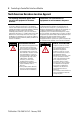
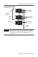
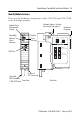
Table Of Contents
- 1756-IN607A-EN-P, ControlLogix ControlNet Interface Module Installation Instructions
- Important User Information
- European Hazardous Location Approval
- North American Hazardous Location Approval
- Environment and Enclosure
- Prevent Electrostatic Discharge
- The ControlNet Interface Module and Redundant Media
- Before You Begin
- Install the Module
- Configure RSLinx Software to Use the USB Port
- Status Indicators
- Specifications
- Additional Resources
- Back Cover
ControlLogix ControlNet Interface Module 9
Publication
1756-IN607A-EN-P - February 2008
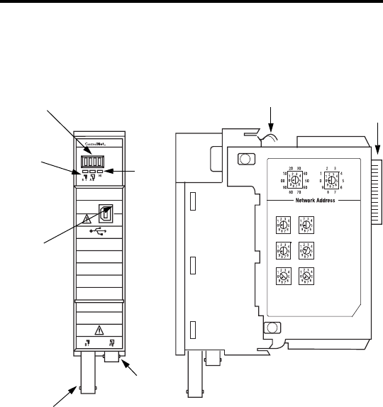
Identify Module Features
These are the hardware components of the 1756-CN2 and 1756-CN2R
series B bridge modules.
Module
Status
Indicator
Channel A
BNC Connector
COAX
00 -
Factory Reset
on Power Up
(Invalid Network Address)
01 - 99
Normal Operation
(Valid Network Address)
Backplane
Connector
Front View
Side View
Module Status
Alphanumeric
Display
ControlNet
Channel
Status
Indicators
USB Port
Channel B
BNC Connector
(1756-CN2R only)
Network Address Switches
(not shown) See page 10.