
Manual
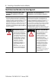
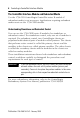
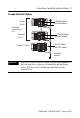
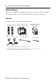
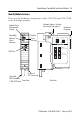
Table Of Contents
- 1756-IN607A-EN-P, ControlLogix ControlNet Interface Module Installation Instructions
- Important User Information
- European Hazardous Location Approval
- North American Hazardous Location Approval
- Environment and Enclosure
- Prevent Electrostatic Discharge
- The ControlNet Interface Module and Redundant Media
- Before You Begin
- Install the Module
- Configure RSLinx Software to Use the USB Port
- Status Indicators
- Specifications
- Additional Resources
- Back Cover
8 ControlLogix ControlNet Interface Module
Publication
1756-IN607A-EN-P - February 2008
Before You Begin
Before you install the module, make sure you know how to handle
the module. Refer to Prevent Electrostatic Discharge on page 5.
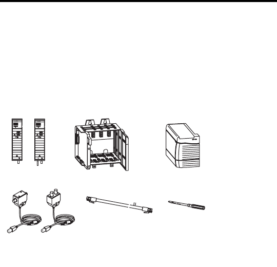
Parts List
You need all of the components shown.
1756-CN2 or 1756-CN2R
Module
1756-A4, 1756-A7, 1756-A10,
1756-A13, or 1756-A17 Chassis
1756-PA72, 1756-PA75,
1756-PB72, or 1756-PB75
Power Supply
1786-TPR, 1786-TPS,
1786-TPYR, or 1786-TPYS Taps
(1)
USB Cable (optional)
Small Screwdriver
(1)
1786-TPS or 1786-TPYS taps are recommended for network connections.
COAX
B
A
OK
B
A
COAX
A
OK
A
(2)
(2)
1756
-CN2 and 1756-CN2R, series
A modules use the 1786-CP cable. However, 1756-CN2 and 1756-CN2R,
series B modules use a USB cable for temporary network connections.
-