
Manual
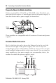
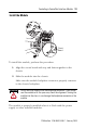
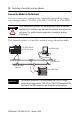
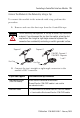
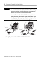
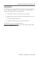
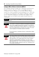
Table Of Contents
- 1756-IN607A-EN-P, ControlLogix ControlNet Interface Module Installation Instructions
- Important User Information
- European Hazardous Location Approval
- North American Hazardous Location Approval
- Environment and Enclosure
- Prevent Electrostatic Discharge
- The ControlNet Interface Module and Redundant Media
- Before You Begin
- Install the Module
- Configure RSLinx Software to Use the USB Port
- Status Indicators
- Specifications
- Additional Resources
- Back Cover
12 ControlLogix ControlNet Interface Module
Publication
1756-IN607A-EN-P - February 2008
Prepare the Chassis for Module Installation
Before you install the 1756-CN2 or 1756-CN2R series B module, you
must install and connect a ControlLogix chassis and power supply. A
four-slot chassis with a power supply is shown here.
These modules are compatible with all versions of chassis and power
supplies.
Determine Module Slot Location
Slot 0 is the first slot and is always the leftmost slot in the rack, the
first slot to the right of the power supply. You can use any size
ControlLogix chassis and install the module in any slot. You can also
install multiple bridge modules in the same chassis. You can install as
many modules as your power supply can accommodate, that is, the
number for which the power supply is rated.
Chassis
Power Supply
Slot 0
Slot 1
Slot 3
Slot 2
Chassis
Power
Supply