Installation Instructions ControlLogix ControlNet Interface Module Catalog Numbers 1756-CN2, 1756-CN2R, Series B Topic Page Important User Information 2 European Hazardous Location Approval 3 North American Hazardous Location Approval 4 Environment and Enclosure 5 Prevent Electrostatic Discharge 5 The ControlNet Interface Module and Redundant Media 6 Understanding Standalone and Redundant Control 6 Example Redundant System 7 Before You Begin 8 Parts List 8 Identify Module Features 9
ControlLogix ControlNet Interface Module Important User Information Solid state equipment has operational characteristics differing from those of electromechanical equipment. Safety Guidelines for the Application, Installation and Maintenance of Solid State Controls (Publication SGI-1.1 available from your local Rockwell Automation sales office or online at http://literature.rockwellautomation.
ControlLogix ControlNet Interface Module 3 European Hazardous Location Approval European Zone 2 Certification (The following applies when the product bears the EEx Marking.) This equipment is intended for use in potentially explosive atmospheres as defined by European Union Directive 94/9/EC.
ControlLogix ControlNet Interface Module North American Hazardous Location Approval The following information applies when operating this equipment in hazardous locations. Informations sur l’utilisation de cet équipement en environnements dangereux. Products marked "CL I, DIV 2, GP A, B, C, D" are suitable for use in Class I Division 2 Groups A, B, C, D, Hazardous Locations and nonhazardous locations only.
ControlLogix ControlNet Interface Module 5 Environment and Enclosure ATTENTION This equipment is intended for use in a Pollution Degree 2 industrial environment, in overvoltage Category II applications (as defined in IEC publication 60664-1), at altitudes up to 2000 meters (6562 feet) without derating. This equipment is considered Group 1, Class A industrial equipment according to IEC/CISPR Publication 11.
ControlLogix ControlNet Interface Module The ControlNet Interface Module and Redundant Media Use the 1756-CN2 ControlLogix ControlNet series B module if redundant media is not necessary. Applications requiring redundant media must use the 1756-CN2R module. Understanding Standalone and Redundant Control You can use the 1756-CN2R series B modules for standalone or redundant control. For standalone control, only one set of modules is required.
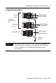
ControlLogix ControlNet Interface Module 7 Example Redundant System Primary Chassis 1756-RM Module 1756-CN2R Module Redundant Control Chassis Pair Secondary Chassis Remote I/O Chassis 1756-RM Module 1756-CN2R Module 1756-CNB/CNBR 1756-CN2 Module 1756-CN2R Module ControlNet Network IMPORTANT The 1756-CN2 and 1756-CN2R series B modules are supported in both the local chassis (primary and secondary) and the remote chassis (I/O chassis) of a ControlLogix redundancy system, revision 16.5x.
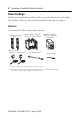
ControlLogix ControlNet Interface Module Before You Begin Before you install the module, make sure you know how to handle the module. Refer to Prevent Electrostatic Discharge on page 5. Parts List You need all of the components shown.
ControlLogix ControlNet Interface Module 9 Identify Module Features These are the hardware components of the 1756-CN2 and 1756-CN2R series B bridge modules. Network Address Switches (not shown) See page 10.
ControlLogix ControlNet Interface Module Set the Module’s Network Address Switches Use a small screwdriver to set the module’s network address switches. For modules in a standalone chassis, you must specify a unique ControlNet network address. You can select an address of 01...99 for modules in a standalone chassis. Address 00 is an invalid ControlNet address. Side of Module Front of Module Top of Module This module’s network address is 23.
ControlLogix ControlNet Interface Module 11 3. Reset the switches to 00. IMPORTANT Do not use the 00 switch setting during normal module operation. 4. Replace the module in the chassis. 5. Apply power to the chassis. 6. After the module status display reads, "Reset Complete-Change Switch Settings," remove power from the chassis. 7. Remove the module from the chassis. 8. Set the switches to their final value. 9. Replace the module in the chassis. 10. Apply power to the chassis.
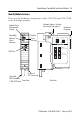
ControlLogix ControlNet Interface Module Prepare the Chassis for Module Installation Before you install the 1756-CN2 or 1756-CN2R series B module, you must install and connect a ControlLogix chassis and power supply. A four-slot chassis with a power supply is shown here. Power Supply Chassis These modules are compatible with all versions of chassis and power supplies.
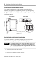
ControlLogix ControlNet Interface Module 13 Install the Module 1 Circuit Board 2 To install the module, perform this procedure. 1. Align the circuit board with top and bottom guides in the chassis. 2. Slide the module into the chassis. Make sure the module backplane connector properly connects to the chassis backplane. ATTENTION Do not force the module into the backplane connector. If you cannot seat the module with firm pressure, check the alignment.
ControlLogix ControlNet Interface Module Connect the Module to the Network You can connect the module to the ControlNet network by using a tap (catalog number 1786-TPR, 1786-TPS, 1786-TPYR, or 1786-TPYS). WARNING If you connect or disconnect the communication cable with power applied to this module or any device on the network, an electrical arc can occur. This could cause an explosion in hazardous location installations. This example shows a ControlNet network using redundant media.
ControlLogix ControlNet Interface Module 15 Connect the Module to the Network by Using a Tap To connect the module to the network with a tap, perform this procedure. 1. Remove and save the dust caps from the ControlNet taps. ATTENTION Do not allow any metal portions of the tap to contact any conductive material. If you disconnect the tap from the module, place the dust cap back on the straight or right-angle connector to prevent the connector from accidentally contacting a metallic grounded surface.
ControlLogix ControlNet Interface Module IMPORTANT To avoid accidentally reversing the tap connections, before making your connection, check the tap drop cable for the label indicating the attached segment. Accidental connection reversals produce incorrect status displays and require troubleshooting. To use modules in a redundant-control chassis pair, you must connect the primary and redundant partner modules to the same network segment.
ControlLogix ControlNet Interface Module 17 Use this flowchart as a guide. Turn the chassis power supply on. Module status indicator red? No See Status Indicators on page 22. Yes Module performs a self-test initialization. TEST Module status indicator red? No Self-test is complete. The status indicator flashes green. Yes Self-test has failed, and the module displays an error message. See pages 23...29. Replace the module.
ControlLogix ControlNet Interface Module Remove the Module To remove the module, perform this procedure. 1. Push on the upper and lower tabs to disengage them. 2. Slide the module out of the chassis. Upper Tab IMPORTANT If you are replacing an existing module with an identical one, and you want to resume identical system operation, you must install the new module with the same ControlNet address in the same slot.
ControlLogix ControlNet Interface Module 19 Install the EDS File The EDS file can be uploaded directly from the module. This feature lets you register the EDS file for your module from within RSLinx software by following the steps listed below. 1. Open RSLinx software, and browse for the module. 2. Right-click the module and select Upload EDS file from device. The Upload EDS wizard opens. 3. Complete the EDS wizard to register the EDS file. The EDS file can also be downloaded from www.ab.com/networks/eds.
ControlLogix ControlNet Interface Module Configure RSLinx Software to Use the USB Port The ControlNet interface module has a USB device port that uses a Type B receptacle. The port is USB 1.1-compatible and runs at 12 Mbps. To use the USB port, you must have RSLinx software, version 2.51 or later, installed on your workstation. Use a USB cable to connect your workstation to the USB port.
ControlLogix ControlNet Interface Module 21 Set Up the USB Driver To configure RSLinx software to use a USB port, you need to first set up a USB driver. To set up a USB driver, perform this procedure. 1. Connect your 1756-CN2 or 1756-CN2R module to your workstation by installing a USB cable in your module’s USB port. The Found New Hardware Wizard dialog appears. 2. Click Install the software automatically (Recommended) and click Next. The software is installed. 3. Click Finish to set up your USB driver. 4.
ControlLogix ControlNet Interface Module Status Indicators The modules have these status indicators.
ControlLogix ControlNet Interface Module 23 Module Status Indicator and Display The Module Status indicator and Module Status display provide diagnostic information. Indicator Display OK Off Red Cause Recommended Action None The module is not communicating due to a power supply fault or internal fault. Reset CompleteChange Switch Settings Module’s network address is set to 00, an invalid ControlNet address. FAIL 1. Check the power supply. 2. Check the cable connectors. 3.
ControlLogix ControlNet Interface Module Indicator Display OK Red (cont.) Stop Service Received Cause Recommended Action A non-redundant module is placed into a redundant secondary chassis. The module was commanded to stop functioning by the redundancy module (RM/SRM). This could occur if a 1756-CN2/R module running Boot code is inserted into a chassis along with a 1756-SRM or 1756-RM module. 1. Remove the non-redundant module from the redundant secondary chassis 2.
ControlLogix ControlNet Interface Module 25 Indicator Display OK Flashing TEST red (cont.) Green Cause Recommended Action Module is executing a power-up test. No action is required. If the display persists for more than 45 seconds, replace the module because it has failed. There is at least one connection to or through the module. No action is required. No action is required. No action is required. OK This is normal operation. INIT PASS Module is initializing.
ControlLogix ControlNet Interface Module Indicator Display Cause OK Green (cont.) Green or flashing green Flashing green MACID SWITCH ERROR Recommended Action Node address switch changed No action is required, but we after you cycled power. recommend that you either return switches to their original settings or replace the module, since this could indicate a latent hardware problem. CPU=xx% This message is the CPU No action is required.
ControlLogix ControlNet Interface Module 27 Indicator Display Cause OK Any Recommended Action Keeper: The network configuration Perform any of these steps: Unconfigured data maintained in flash • Use RSNetWorx software to memory by the keeper object download or update the has been erased or corrupted. keeper object in the module. • See Reset the Module to the Original Factory Settings on page 10.
ControlLogix ControlNet Interface Module Indicator Display OK Any (cont.) Keeper: Signature Mismatch Keeper: None Valid on Network (1) Cause Recommended Action The network configuration data maintained in flash memory by the keeper object does not match the current network configuration. Use RSNetWorx software to download or update the keeper object in the module, or see Reset the Module to the Original Factory Settings on page 10. There is a valid master keeper on the network.
ControlLogix ControlNet Interface Module 29 ControlNet Channel Status Indicators The ControlNet channel status indicators appear in one of these states: • Steady - status indicator is on continuously in the defined state. • Alternating - while viewed together, the two indicators simultaneously alternate between the two defined states. The two indicators are always in opposite states, out of phase.
ControlLogix ControlNet Interface Module ControlNet Channel Troubleshooting (A OR B) Cause Action Off Channel has been disabled. Program network for redundant media, if required. Steady green This is normal operation. No action is required. Flashing green/off Temporary errors exist. None; unit will self-correct. Node is not configured to go online.
ControlLogix ControlNet Interface Module 31 Specifications ControlLogix ControlNet Bridge Module - 1756-CN2, 1756-CN2R, Series B Attribute Value Connectors 1756-CN2 1756-CN2R 1 - ControlNet BNC 2 - ControlNet BNC USB port USB 1.1 USB Device USB Series B Receptacle Recommended USB cable for USB port Samtec cable, P/N RSP-199350 ControlNet communication rate 5 MB Weight, approx. 1756-CN2 1756-CN2R 0.260 kg (0.57 lb) 0.293 kg (0.
ControlLogix ControlNet Interface Module ControlLogix ControlNet Bridge Module - 1756-CN2, 1756-CN2R, Series B Attribute Value Power dissipation, max 1756-CN2 1756-CN2R 5.6 W 6.6 W Thermal dissipation, max 1756-CN2 1756-CN2R 19.1 BTU/hr 22.5 BTU/hr Backplane current 1756-CN2 1756-CN2R 1.1 A @ 5.1V dc 1.3 A @ 5.
ControlLogix ControlNet Interface Module 33 Environmental Specifications Attribute Value Temperature, operating IEC 60068-2-1 (Test Ad, Operating Cold), IEC 60068-2-2 (Test Bd, Operating Dry Heat), IEC 60068-2-14 (Test Nb, Operating Thermal Shock): 0…60 °C (32…140 °F) Temperature, storage IEC 60068-2-1 (Test Ab, Unpackaged Nonoperating Cold), IEC 60068-2-2 (Test Bb, Unpackaged Nonoperating Dry Heat), IEC 60068-2-14 (Test Na, Unpackaged Nonoperating Thermal Shock): -40…85 °C (-40…185 °F) Relative humid
ControlLogix ControlNet Interface Module Certifications Certification Value Certifications (when product UL is marked)(1) UL Listed Industrial Control Equipment. See UL File E65584. UL Listed for Class I, Division 2 Group A,B,C,D Hazardous Locations. See UL File E194810 cULus UL Listed Industrial Control Equipment, certified for US and Canada. See UL File E65584. UL Listed for Class I, Division 2 Group A,B,C,D Hazardous Locations, certified for U.S. and Canada.
ControlLogix ControlNet Interface Module 35 Additional Resources These documents contain additional information concerning related Rockwell Automation products. Resource Description Industrial Automation Wiring and Grounding Guidelines, publication 1770-4.
Rockwell Automation Support Rockwell Automation provides technical information on the Web to assist you in using its products. At http://support.rockwellautomation.com, you can find technical manuals, a knowledge base of FAQs, technical and application notes, sample code and links to software service packs, and a MySupport feature that you can customize to make the best use of these tools.