Installation Instructions ControlLogix® Battery Module Catalog Number: 1756-BATM IMPORTANT Installation instructions ship with each component. If you want other documentation, you must order it separately. Refer to Additional Manuals on page 31.
ControlLogix® Battery Module Important User Information Solid state equipment has operational characteristics differing from those of electromechanical equipment. Safety Guidelines for the Application, Installation and Maintenance of Solid State Controls (Publication SGI-1.1 available from your local Rockwell Automation sales office or online at http://www.ab.com/manuals/gi) describes some important differences between solid state equipment and hard-wired electromechanical devices.
ControlLogix® Battery Module 3 WARNING ! When you insert or remove the module while backplane power is on, an electrical arc can occur. This could cause an explosion in hazardous location installations. Be sure that power is removed or the area is nonhazardous before proceeding. Repeated electrical arcing causes excessive wear to contacts on both the module and its mating connector. Worn contacts may create electrical resistance that can affect module operation.
ControlLogix® Battery Module Equipment that You Need The equipment that you need to install the battery module depends on how you mount the module.
ControlLogix® Battery Module 5 What You Need to Do Before you install a battery module, do these preliminary tasks: ✓ Install a ControlLogix chassis according to the ControlLogix Chassis Installation Instructions, publication 1756-IN080. ✓ Install a ControlLogix power supply according to the corresponding installation instructions: Install this power supply: According to this publication: 1756-PA72 ControlLogix Power Supplies Installation Instructions, publication 1756-5.
ControlLogix® Battery Module To install a battery module, do these tasks: Make Sure that You Have All the Components Select a Location for the Module Select a Mounting Option Mount the Battery Module to a DIN Rail Mount the Battery Module Directly to a Panel Attach the Cable to the Controller Install the Battery Assembly Check the BAT LED Estimate Battery Life Publication 1756-IN576B-EN-P - September 2003
ControlLogix® Battery Module 7 Make Sure that You Have All the Components The 1756-BATM battery module includes these components: Component: Description: battery module The cable is already attached to the module. The cable includes a ferrite core for noise suppression. The ferrite core is close to the end of the cable.
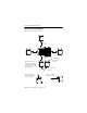
ControlLogix® Battery Module Select a Location for the Module Mount the battery module as follows: ≥ 5.1 cm (2.0 in) ≥ 5.1 cm ≥ 5.1 cm (2.0 in) (2.0 in) ≥ 5.1 cm (2.0 in) Mount below the chassis, if possible. This minimizes the temperature of the module and prolongs the life of the battery assembly. On a horizontal panel, mount the module with the door facing up. 1 m cable connects battery module to controller OK to mount next to each other Leave space to remove the battery assembly. ≥ 7.
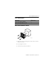
ControlLogix® Battery Module 9 Select a Mounting Option If you want to: Then go to page: Mount the Battery Module to a DIN Rail 9 Mount the Battery Module Directly to a Panel 11 Mount the Battery Module to a DIN Rail 31306-M 1. Align the holes on the mounting brackets with the holes on the back of the battery module. 2. Insert and tighten the screws. 3. Attach the battery module to the DIN rail.
ControlLogix® Battery Module 4. Attach a DIN rail lock (A-B catalog number 1492-EA35) on each side of the battery module. 31330 5. Ground the battery module to the enclosure. 6. Go to “Attach the Cable to the Controller” on page 14.
ControlLogix® Battery Module 11 Mount the Battery Module Directly to a Panel To mount the battery module directly to a panel: • Drill the Mounting Holes • Mount the Battery Module Drill the Mounting Holes 1. Are you installing the battery module above existing components? If: Then: Yes Protect the existing components from metal chips that may fall as you drill the mounting holes. No Go to step 2. 2. On the panel of the enclosure, mark the holes for the mounting tabs of the battery module.
ControlLogix® Battery Module Mount the Battery Module 1. To make an electrical connection between the battery module and the enclosure, scrape the paint off the panel of the enclosure. 2. Install the hardware for the top mounting tabs. M4 or M5 (#10 or #12) phillips screw, flat washer, and split lock-washer 31301-M 3. Slide the top tabs of the battery module over the screws. 4. Tighten the screws.
ControlLogix® Battery Module 13 5. Install and tighten the hardware for the bottom tab.
ControlLogix® Battery Module Attach the Cable to the Controller An electrical arc can occur when you: WARNING ! • connect or disconnect the battery • connect or disconnect the battery module from the controller This could cause an explosion in hazardous location installations. Be sure that power is removed or the area is nonhazardous before proceeding.
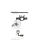
ControlLogix® Battery Module 15 top white lead middle black lead (-) bottom red lead (+) to the battery module 3. Attach the cable from the battery module to the controller.
ControlLogix® Battery Module Install the Battery Assembly ATTENTION ! IMPORTANT Only install a 1756-BATA battery. If you install a different battery, you may damage the controller Connect the battery assembly to the battery module only when you are ready to use it. Even if the battery module is not connected to the controller, the battery assembly begins to discharge once you connect it to the battery module. 1. Remove the door of the battery module.
ControlLogix® Battery Module 17 2. Put the battery assembly into the battery module with the wires facing outward. WARNING ! When you connect or disconnect the battery an electrical arc can occur. This could cause an explosion in hazardous location installations. Be sure that power is removed or the area is nonhazardous before proceeding.
ControlLogix® Battery Module 5. Write on the battery label the date that you install the battery assembly. EXAMPLE 7/9/01 Battery was installed on this date. 6. Attach the label to the front of the battery module.
ControlLogix® Battery Module 19 Check the BAT LED 1. Turn on the chassis power. BAT LED 31303-M 2. Is the BAT LED off ? If: Then: Yes The battery module is correctly installed. No Go to step 3. 3. Check that the battery module is correctly connected to the controller. 4. Check that the battery assembly is correctly connected to the battery module. 5. If the BAT LED remains on, install another battery assembly (catalog # 1756-BATA). 6.
ControlLogix® Battery Module Estimate Battery Life When the battery is about 50 percent discharged, the controller provides the following warnings: • On the front of the controller, the BAT LED turns on (solid red). • A minor fault occurs (type 10, code 10). To estimate how long the battery will support the memory of the controller: 1. Determine the temperature (° C) 1 in. below the battery module. 2. Determine the percentage of time that the controller is powered off per week.
ControlLogix® Battery Module 21 If the BAT LED turns on when you apply power to the controller, the battery life may be less then the table below indicates. Some of the battery life may have been used up while the controller was off and unable to turn on the BAT LED.
ControlLogix® Battery Module Specifications Description: Value: Supply Power input power 15 mA max @ 5.1V dc output power 20 mA max @ 3.
ControlLogix® Battery Module 23 Description: Value: Non-Operating Shock IEC 60068-2-27 (Test Ea, Unpackaged Shock): panel mounted 50g DIN rail mounted 15g Emissions CISPR 11: • Group 1, Class A ESD Immunity IEC 61000-4-2: • 6kV contact discharges • 8kV air discharges Radiated RF Immunity IEC 61000-4-3: • 10V/m with 1kHz sine-wave 80%AM from 80MHz to 2000MHz Enclosure Type Rating None (open-style) Cable 1m category 3(1) Replacement Battery Assembly 1756-BATA (10g lithium) Publication 1756-
ControlLogix® Battery Module Description: Value: Certifications: UR UL Recognized Component Industrial Control Equipment CSA CSA Certified Process Control Equipment CSA CSA Certified Process Control Equipment for Class I, Division 2 Group A,B,C,D Hazardous Locations CE(2) European Union 89/336/EEC EMC Directive, compliant with: • EN 50082-2; Industrial Immunity • EN 61326; Meas./Control/Lab.
ControlLogix® Battery Module 25 Mounting Template Cut out the following template and use it to mark the holes for the mounting tabs of the battery module.
ControlLogix® Battery Module Publication 1756-IN576B-EN-P - September 2003
ControlLogix® Battery Module 27 Dimensions 10.9 mm (0.43 in) 53.1 mm (2.09 in) 2x R2.8 mm 2x R(0.11 in) 93.7 mm (3.69 in) 105.7 mm (4.16 in) 72.9 mm (2.87 in) 37.6 mm (1.48 in) 74.9 mm (2.95 in) 31300 Ø 5.5 mm Ø (0.217 in) 74.2 mm (2.92 in) 86.4 mm (3.
ControlLogix® Battery Module Environment and Enclosure Information ATTENTION ! Environment and Enclosure This equipment is intended for use in a Pollution Degree 2 industrial environment, in overvoltage Category II applications (as defined in IEC publication 60664-1), at altitudes up to 2000 meters without derating. This equipment is considered Group 1, Class A industrial equipment according to IEC/CISPR Publication 11.
ControlLogix® Battery Module 29 European Hazardous Location Approval European Zone 2 Certification This equipment is intended for use in potentially explosive atmospheres as defined by European Union Directive 94/9/EC.
ControlLogix® Battery Module North American Hazardous Location Approval The following information applies when operating this equipment in hazardous locations: Informations sur l’utilisation de cet équipement en environnements dangereux : Products marked “CL I, DIV 2, GP A, B, C, D” are suitable for use in Class I Division 2 Groups A, B, C, D, Hazardous Locations and nonhazardous locations only.
ControlLogix® Battery Module 31 Additional Manuals This product has the following manuals: • Logix5000 Controllers Common Procedures, publication 1756-PM001 • Logix5000 Controllers General Instructions Reference Manual, publication 1756-RM003 • ControlLogix System User Manual, publication 1756-UM001 If you want to: Then: view a manual Visit either of these locations: download a manual • www.ab.com/manuals • www.theautomationbookstore.
Rockwell Automation Support Rockwell Automation provides technical information on the web to assist you in using our products. At http://support.rockwellautomation.com, you can find technical manuals, a knowledge base of FAQs, technical and application notes, sample code and links to software service packs, and a MySupport feature that you can customize to make the best use of these tools.