
Instruction Manual

99Publication 1753-UM001C-EN-P - March 2010 99
Chapter
10
Wire the 1753-OW8 Relay Output Module
Introduction
Safety-related Relay
Outputs
The module has 8 isolated relay outputs whose status is indicated via
status indicators.
An output is in a safety state when it is de-energized. When a fault
occurs, all outputs are switched off. Errors in one or more channels
are indicated by the FAULT status indicator. In addition, the system
status can be evaluated in the user program.
If the 1753-OW8 module faults, all 8 outputs are switched off. This is
indicated by the FAULT status indicator.
Each output has 2 safety relays with positively guided contacts and
one MSR type relay. Internal, non-replaceable fuses are used to limit
the switching current of the output contacts to 60% (3.15 A) of the
maximum admissible AC switching current. For DC switching, the
relay contact circuits must be additionally equipped with an external
fuse rated no higher than the maximum admissible DC switching
capacity.
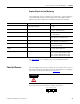
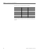
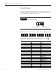
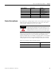
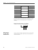
Terminal Connections
See the wire size and terminal torques specifications on page 294.
Relay outputs are connected to these terminals.
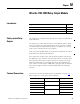
Topic Page
Safety-related Relay Outputs 99
Terminal Connections 99
Voltage Supply Considerations 100
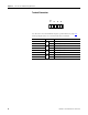
Terminal Number Designation Relay Output
1 DO1 Contact 1, terminal A
2 Contact 1, terminal B
3 DO2 Contact 2, terminal A
4 Contact 2, terminal B
5 DO3 Contact 3, terminal A
6 Contact 3, terminal B