
Instruction Manual

96 Publication 1753-UM001C-EN-P - March 2010
Chapter 9 Wire the 1753-IF8XOF4 Analog I/O Module
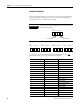
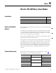
Terminal Connections
Analog cabling should be no more than 300 m (984 ft) in length and
must be shielded, twisted-pair cables for each measurement input.
The shields must be connected at one end.
See the wire size and terminal torques specifications on page 292
.
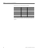
Analog inputs (AI) are connected to these terminals.
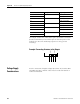
IMPORTANT
Short-circuit unused input channels to the reference pole by
connecting wire jumpers.
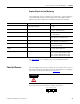
Terminal Number Designation Function
1 T1 Sensor supply 1
2 I1 Analog input 1
3 L- Reference pole input 1
4 T2 Sensor supply 2
5 I2 Analog input 2
6 L- Reference pole input 2
7 T3 Sensor supply 3
8 I3 Analog input 3
9 L- Reference pole input 3
10 T4 Sensor supply 4
11 I4 Analog input 4
12 L- Reference pole input 4
13 T5 Sensor supply 5
14 I5 Analog input 5
15 L- Reference pole input 5
16 T6 Sensor supply 6
17 I6 Analog input 6
18 L- Reference pole input 6
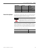
AI
T1 I1 L- T2 I2 L-
41 42 43 44 45 46
Wire Jumpers
Wire Jumpers
I1T1 L-
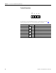
AI
L- T2 I2 I3T3 L-L- T4 I4 I5T5 L-L- T6 I6 I7T7 L-L- T8 I8
AI AI AI
7891011121 2 3 4 5 6 13 14 15 16 17 18 19 20 21 22 23 24