
Instruction Manual

Publication 1753-UM001C-EN-P - March 2010 93
Wire and Configure the 1753-IB16XOB8 Module Chapter 8
Required Signals for Line Monitoring
Line monitoring must be configured by using these system signals for
1753-IB16XOB8 modules on the Outputs tab of the digital outputs
Signal Connections dialog box in RSLogix Guard PLUS! software.
See Appendix B
for a complete list of 1753-IB16XOB8 module
variables.
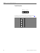
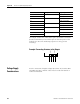
Pulse Test Sources
The two digital pulse test sources (PO) can be used for short-circuit or
line break monitoring of digital inputs. For information on configuring
pulse test sources for line control, see Chapter
11.
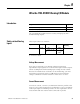
Each output has four terminals for wiring connections.
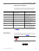
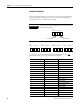
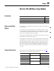
Name Description Setting
DO.LSLB period The time between steps in Line Short Line
Break (LSLB) monitoring
Values in one second increments from
1…100.
DO.LSLB time The duration of LSLB monitoring Values in one millisecond increments from
0…50 ms. The default is 0 ms.
DO[xx].2-pole Configures the module for 2-pole operation 1 = 2-pole operation.
0 = 1-pole operation.
DO[xx].+Value Output value for DO channels (DO+) 1-pole (Value: 0 or 1).
2-pole, identical to DO- (Value: 0 or 1).
DO[xx].-Value Output value for DO channels (DO-) 1-pole (Value: 0 or 1).
2-pole, identical to DO+ (Value: 0 or 1).
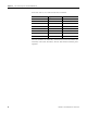
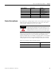
DO[xx].LSLB monitoring Configures line control 1 = set for LSLB (line control)
0 = no LSLB (line control)
DO[xx].LS monitoring with reduced
voltage
Configures line control with reduced voltage 1 = reduced signal voltage level
0 = normal signal voltage level
DO[xx][xx].in pairs Configures line control with channel pairs Pair 1 = channel 1 [01] and channel 2 [02]
Pair 2 = channel 3 [03] and channel 4 [04]
Pair 3 = channel 5 [05] and channel 6 [06]
Pair 4 = channel 7 [07] and channel 8 [08]
ATTENTION
Pulse test sources must not be used as safety-related outputs.
11112222
25 26 27 28 29 30 3231