
Instruction Manual

Publication 1753-UM001C-EN-P - March 2010 91
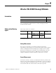
Wire and Configure the 1753-IB16XOB8 Module Chapter 8
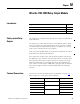
Monitor for Line Short Line
Break
The Line Short Line Break (LSLB) monitoring measures the impedance
of a load and allows the modules to detect the following faults, when
LSLB monitoring is configured by using the system variable
DO[xx].LSLB:
• Short-circuit between DO+ and DO-
• Short-circuit DO+ and external L+
• Short-circuit between DO+ and external L-
• Short-circuit between DO- and external L+
• Short-circuit between DO- and external L-
• Line break between DO+ and DO-
Line monitoring of the digital outputs is possible only when outputs
are configured for 2-pole operation and both poles DO[xx]- and
DO[xx]+ are wired to a load. A detected line fault is reported in the
system signal DO[xx].+Error Code or DO[xx].-Error Code. See
Appendix B
for information on system signals.
There are two kinds of line monitoring.
• Line monitoring for lamp loads and inductive loads
• Line monitoring for resistive, capacitive loads
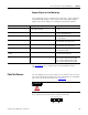
For both types, you must configure a period and time for line
monitoring by using the system signal variables described on page 93
.
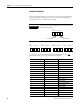
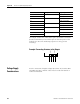
Line Monitoring for Lamp and Inductive Loads
For short-circuit detection, a 24V impulse with a duration of 500 μs is
switched in the output circuit. Afterwards, a 10V signal is set for the
duration of the monitoring time to detect a line break.
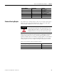
To configure this type of line monitoring:
• set a DO.LSLB period and DO.LSLB time.
• set the output DO[xx].2-pole signal to 1 (TRUE).
• set the output DO[xx].LSLB monitoring signal to 1 (TRUE).
• set the output DO[xx].LS monitoring with reduced voltage signal
to 0 (FALSE).
See Required Signals for Line Monitoring
on page 93.