
Instruction Manual


86 Publication 1753-UM001C-EN-P - March 2010
Chapter 8 Wire and Configure the 1753-IB16XOB8 Module
Safety-related Digital
Outputs
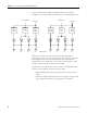
The module has 8 digital output pairs, each with a positive- and
negative-switching output. The digital outputs are not electrically
isolated.
An output is in the safe state when it is de-energized. Therefore,
outputs are switched off when a fault that affects the safety control of
those outputs occurs.
If an overload occurs, the affected output is switched off. If the total
current exceeds 9 A, all eight outputs are switched off. When the
overload is eliminated, the outputs are activated again according to
their current software-driven state.
Configuration
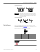
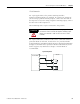
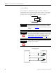
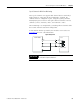
The digital outputs can be configured three ways.
• 1-pole switch (no line monitoring)
• 2-pole switch (with or without line monitoring)
• 3-pole switch (2-pole with common reference)
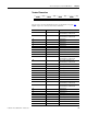
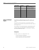
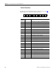
63 LS+ Sensor supply for inputs 13…16
40 mA buffered/1 A unbuffered
64 LS+ Sensor supply for inputs 13…16
40 mA buffered/1 A unbuffered
65 13 Digital input 13
66 14 Digital input 14
67 15 Digital input 15
68 16 Digital input 16
69 L- Reference pole
70 L- Reference pole
71 Ground Shield
72 Ground Shield
Terminal Number Designation Function