
Instruction Manual

Publication 1753-UM001C-EN-P - March 2010 85
Wire and Configure the 1753-IB16XOB8 Module Chapter 8
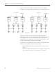
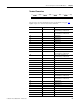
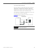
Terminal Connections
See the wire size and terminal torques specifications on page 290.
Digital inputs are connected to these terminals.
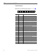
Terminal Number Designation Function
33 LS+ Sensor supply for inputs 1… 4
40 mA buffered/1 A unbuffered
34 LS+ Sensor supply for inputs 1…4
40 mA buffered/1 A unbuffered
35 1 Digital input 1
36 2 Digital input 2
37 3 Digital input 3
38 4 Digital input 4
39 L- Reference pole
40 L- Reference pole
41 Ground Shield
42 Ground Shield
43 LS+ Sensor supply for inputs 5…8
40 mA buffered/1 A unbuffered
44 LS+ Sensor supply for inputs 5…8
40 mA buffered/1 A unbuffered
45 5 Digital input 5
46 6 Digital input 6
47 7 Digital input 7
48 8 Digital input 8
49 L- Reference pole
50 L- Reference pole
51 Ground Shield
52 Ground Shield
53 LS+ Sensor supply for inputs 9…12
40 mA buffered/1 A unbuffered
54 LS+ Sensor supply for inputs 9…12
40 mA buffered/1 A unbuffered
55 9 Digital input 9
56 10 Digital input 10
57 11 Digital input 11
58 12 Digital input 12
59 L- Reference pole
60 L- Reference pole
61 Ground Shield
62 Ground Shield
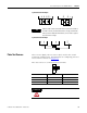
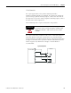
LS+ LS+ 1 2 3 4 L-L-
33 34 35 36 37 38 39 40 41 42
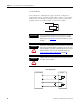
43 44 45 46 47 48 49 50 51 52 53 54 55 56 57 58 59 60 61 62 63 64 65 66 67 68 69 70 71 72
LS+ LS+ 5 6 7 8 L-L- LS+ LS+ 9 10 11 12 L-L- LS+ LS+ 13 14 15 16 L-L-