
Instruction Manual

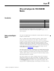

Publication 1753-UM001C-EN-P - March 2010 81
Wire and Configure the 1753-IB8XOB8 Module Chapter 7
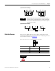
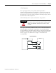
1-pole Connection Examples
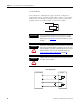
2-pole Connection Example
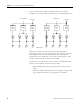
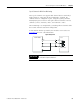
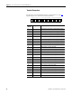
Pulse Test Sources
There are two digital pulse test sources (PO) used for line control
monitoring of digital inputs. For information on configuring pulse test
sources for line control, see Chapter
11.
Pulse test sources are connected to these terminals.
TIP
Inductive loads can be connected without a protection diode on
the load. However, Rockwell Automation strongly recommends
that a protection diode be fitted directly to the load to suppress
any interference voltage.
DO 1
DO 2
DO 3
DO 4
L-
L-
S+
DO 4-
DO 8-
DO4-
DO8-
DO4
DO8
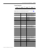
Terminal Number Designation Function
1 L- Reference pole
2 1 Pulsed output 1
3 2 Pulsed output 2
ATTENTION
Pulse test sources must not be used as safety-related outputs.
1L- S+
PO
24-8-
123456
123456
DO