
Instruction Manual

80 Publication 1753-UM001C-EN-P - March 2010
Chapter 7 Wire and Configure the 1753-IB8XOB8 Module
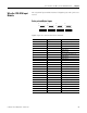
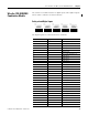
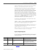
Terminal Connections
See the wire size and terminal torques specifications on page 290.
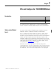
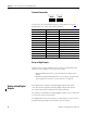
Digital outputs are connected to these terminals.
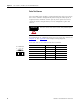
For connection of a load, the reference pole L- of the channel group
must be used. Although L- at terminals 7 and 12 and at terminals 13
and 18 are connected internally to L- on the power supply input, it is
strictly recommended to use 7 and 12 for outputs 1…4 only and 13
and 18 for outputs 5…8 only. EMC testing was performed in this
manner.
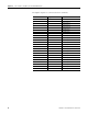
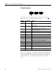
Terminal
Number
Designation Function
4 4- Negative switching digital output 4 (for increased load or
bi-polar output)
5 8- Negative switching digital output 8 (for increased load or
bi-polar output)
6 S+ Reference pole for negative switching outputs
(short-circuit protection)
7 L- Reference pole for positive-switching outputs
8 1 Digital output 1
9 2 Digital output 2
10 3 Digital output 3
11 4 Digital output 4 (for increased load or bi-polar output)
12 L- Reference pole for positive-switching outputs
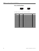
13 L- Reference pole for positive-switching outputs
14 5 Digital output 5
15 6 Digital output 6
16 7 Digital output 7
17 8 Digital output 8 (for increased load or bi-polar output)
18 L- Reference pole for positive-switching outputs
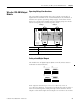
1L- L-
DO
234
789101112
789101112
5L- L-
DO
678
13 14 15 16 17 18
13 14 15 16 17 18
1L- S+
PO
24-8-
123456
123456
DO