
Instruction Manual

78 Publication 1753-UM001C-EN-P - March 2010
Chapter 7 Wire and Configure the 1753-IB8XOB8 Module
Terminal Connections
See the wire size and terminal torques specifications on page 290.
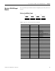
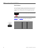
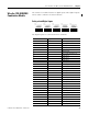
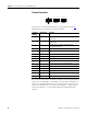
Digital inputs are connected to these terminals.
Surge on Digital Inputs
An EN 61000-4.5 surge impulse can be read as a short-duration HI
signal in some modules. To avoid an error, either:
• install shielded input lines to prevent effects of surges in the
system.
• implement software filtering in the user program. A signal must
be present for at least two cycles before it is evaluated.
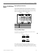
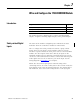
Safety-related Digital
Outputs
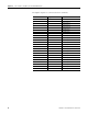
The module has 8 positive-switching digital outputs that switch
+24V DC and two negative-switching digital outputs that switch
24V COM. Their status is indicated via status indicators.
The positive and negative-switching digital outputs can be connected
in a one-pole or two-pole manner.
If configured for one-pole operation, use the reference pole L- for the
positive-switching outputs and reference pole S+ for the
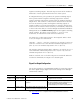
Terminal Number Designation Function
19 LS+ Sensor supply for inputs 1… 4
20 1 Digital input 1
21 2 Digital input 2
22 3 Digital input 3
23 4 Digital input 4
24 L- Reference pole
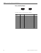
25 LS+ Sensor supply for inputs 5 …8
26 5 Digital input 5
27 6 Digital input 6
28 7 Digital input 7
29 8 Digital input 8
30 L- Reference pole
1LS+ L-
DI
234
19 20 21 22 23 24
19 20 21 22 23 24
LS+ 5 L-
DI
678
25 26 27 28 29 30
25 26 27 28 29 30