
Instruction Manual

68 Publication 1753-UM001C-EN-P - March 2010
Chapter 5 Wire the GuardPLC 2000 Controller and I/O
Wire the 1755-HSC Counter
Modules
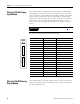
This module contains 2 high-speed counters and 4 digital outputs.
Although the 4 digital outputs are located on the 1755-HSC module,
they cannot be driven by counter presets. The 4 digital outputs are
driven by software, just as on the 1755-IB24XOB16 module.
The nominal current per output is limited to ≤ 0.5 A. Currents > 0.5 A
are regarded as overload. The overload is limited to ≤ 11 A per
output, or ≤ 2 A if all four outputs are overloaded at the same time.
With an overload of 2 A, the output voltage drops to 18V.
All counter common reference poles, C-, share the same path. All
digital output common reference poles, L-, share the same path, but
are electrically isolated from the C- pins.
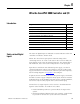
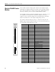
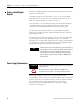
Terminal Number Designation Function
1 C- Common reference pole
2 A1 Signal input for counter 1
3 B1 Counting direction input for counter 1
4 Z1 Reset input for counter 1
5 C1 no function
6 C- Common reference pole
7 C- Common reference pole
8 C- Common reference pole
9 C- Common reference pole
10 C- Common reference pole
11 A2 Signal input for counter 2
12 B2 Counting direction input for counter 2
13 Z2 Reset input for counter 2
14 C2 no function
15 C- Common reference pole
16 C- Common reference pole
17 C- Common reference pole
18 C- Common reference pole
19 L- Reference pole for digital outputs
20 1 Digital output 1
21 2 Digital output 2
22 3 Digital output 3
23 4 Digital output 4
24 L- Reference pole for digital outputs
25 L- Reference pole for digital outputs
26 L- Reference pole for digital outputs
27 L- Reference pole for digital outputs
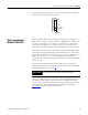
RUN
ERR
1755-
HSC
1
2
3
4
5
6
7
8
9
A1
B1
Z1
C1
C-
C-
C-
C-
10
11
12
13
14
15
16
17
18
19
20
21
22
23
24
25
26
27
L-
1
2
3
4
L-
L-
L-
L-
C-
A2
B2
Z2
C2
C-
C-
C-
C-
C-