
Instruction Manual

Publication 1753-UM001C-EN-P - March 2010 67
Wire the GuardPLC 2000 Controller and I/O Chapter 5
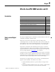
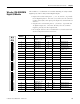
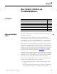
There are 4 reference poles for the 8 outputs. A pair of outputs share
a reference pole as shown below.
Each group of 2 outputs is electrically isolated from the others.
These outputs Share these Reference Poles
1 and 2 O1- and O2-
3 and 4 O3- and O4-
5 and 6 O5- and O6-
7 and 8 O7- and O8-
IMPORTANT
If an unused channel is defined as a current output (software
configuration set to current output), the output channel has to
be short-circuited. Place jumpers into these outputs and tighten
the screws.
IMPORTANT
If an unused channel is defined as a voltage output (software
configuration set to voltage output), the unused outputs must be
left open. Short-circuiting a unused voltage output may cause
damage to the output.
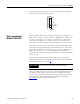
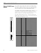
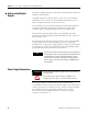
Terminal Number Designation Function
1 O1+ Analog output 1
2 O1- Group 1 reference pole
3 O2+ Analog output 2
4 O2- Group 1 reference pole
5 O3+ Analog output 3
6 O3- Group 2 reference pole
7 O4+ Analog output 4
8 O4- Group 2 reference pole
9 shield connection signal ground
10 O5+ Analog output 5
11 O5- Group 3 reference pole
12 O6+ Analog output 6
13 O6- Group 3 reference pole
14 O7+ Analog output 7
15 O7- Group 4 reference pole
16 O8+ Analog output 8
17 O8- Group 4 reference pole
18 shield connection signal ground
RUN
ERR
1755-
OF8
1
2
3
4
5
6
7
8
9
O1-
O2+
O2-
O3+
O4+
10
11
12
13
14
15
16
17
18
O1+
O3-
O4-
O5-
O6+
O6-
O7+
O8+
O5+
O7-
O8-