
Instruction Manual

66 Publication 1753-UM001C-EN-P - March 2010
Chapter 5 Wire the GuardPLC 2000 Controller and I/O
Wire the 1755-IF8 Analog
Input Module
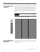
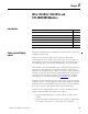
This module features 8 single-ended analog inputs or 4 differential
analog inputs. Two-wire or four-wire transmitters can be used. The
devices cannot be powered from the GuardPLC module. An external
power supply is required for all analog transmitters. Single-ended
transmitters connect between the Ix+ and I- terminals. For example:
pins 1 and 2, 3 and 4, 5 and 6. Differential transmitters connect
between Ix+ and x- terminals. For example, pins 1 and 10, 3 and 12, 5
and 14.
All reference poles (I-) are internally connected.
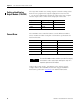
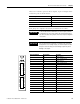
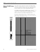
Wire the 1755-OF8 Analog
Output Module
This module features 8 analog outputs. Devices cannot be powered
from the 1755-OF8 module. An external power supply is required for
all analog output devices.
IMPORTANT
Unused channels must be short-circuited. See page 63.
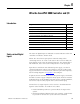
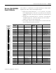
Terminal Number Designation Function
1 I1+ Analog input 1
2 I- Reference pole for input 1
3 I2+ Analog input 2
4 I- Reference pole for input 2
5 I3+ Analog input 3
6 I- Reference pole for input 3
7 I4+ Analog input 4
8 I- Reference pole for input 4
9 shield connection signal ground
10 I5+/1- Analog input 5
11 I- Reference pole for input 5
12 I6/2- Analog input 6
13 I- Reference pole for input 6
14 I7+/3- Analog input 7
15 I- Reference pole for input 7
16 I8+/4- Analog input 8
17 I- Reference pole for input 8
18 shield connection signal ground
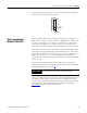
RUN
ERR
1755-
IF8
1
2
3
4
5
6
7
8
9
I-
I2+
I-
I3+
I-
I4+
I-
10
11
12
13
14
15
16
17
18
I1+
I-
I6+/2-
I-
I7+/3-
I-
I8+/4-
I-
I5+/1-