
Instruction Manual

61Publication 1753-UM001C-EN-P - March 2010 61
Chapter
5
Wire the GuardPLC 2000 Controller and I/O
Introduction
Safety-related Digital
Inputs
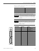
The status of digital inputs is indicated via status indicators when the
controller or module is in Run mode.
Follow the closed-circuit principle for external wiring when
connecting sensors. To create a safe state in the event of a fault, the
input signals revert to the de-energized state (0). The external line is
not monitored, but a wire break is interpreted as a safe (0) signal.
Input devices with their own dedicated power supply can also be
connected instead of contacts. The reference pole (L-) of the power
supply must then be connected to the reference pole of the input (L-).
See the wiring diagrams in Appendix
C for examples.
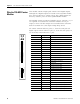
In general, the LS+ terminals, not L+ on the power supply connection,
should be used to supply voltage for safety inputs. Each LS+ features
individual short-circuit and EMC protection. Due to current limitations,
use LS+ for only the safety inputs on the same terminal plug.
An EN 61000-4.5 surge impulse can be read as a short-duration HI
signal in some modules. To avoid an error, either:
• install shielded input lines to prevent effects of surges in the
system.
• implement software filtering in the user program. A signal must
be present for at least two cycles before it is evaluated.
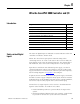
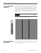
Topic Page
Safety-related Digital Inputs 61
Safety-related Digital Outputs 62
Safety-Related Analog Inputs (1755-IF8) 62
High-speed Counter Module (1755-HSC) 63
Safety-related Analog Output Module (1755-OF8) 64
Current Draw 64
Wire the 1755-IB24XOB16 Digital I/O Module 65
Wire the 1755-IF8 Analog Input Module 66
Wire the 1755-OF8 Analog Output Module 66
Wire the 1755-HSC Counter Modules 68