
Instruction Manual

56 Publication 1753-UM001C-EN-P - March 2010
Chapter 4 Wire GuardPLC 1600, GuardPLC 1800, and GuardPLC 1200 Controllers
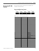
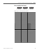
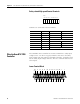
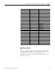
Safety-related Digital Output Terminals
Digital outputs are connected to these terminals.
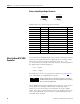
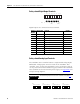
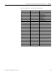
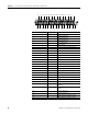
Safety-related Analog Input Terminals
The GuardPLC 1800 controller features 8 single-ended analog inputs.
Differential analog inputs cannot be used on the GuardPLC 1800
controller. Two- or four-wire transmitters can be used. These devices
can be powered from the transmitter supply terminal of the GuardPLC
1800 controller or from an external power supply. See Appendix
C for
example wiring diagrams.
Terminal
Number
Designation Function Current
1 L- Reference pole —
2 1 Digital output 1 0.5 A
3 2 Digital output 2 0.5 A
4 3 Digital output 3 0.5 A
5 4 Digital output 4 (for increased load) 2.0 A
6 5 Digital output 5 0.5 A
7 6 Digital output 6 0.5 A
8 7 Digital output 7 0.5 A
9 8 Digital output 8 (for increased load) 2.0 A
10 L- Reference pole —
IMPORTANT
Unused analog inputs must be short-circuited. See page 51.
123456
1234
1L- L-DO 2
(2 A)(2 A)
345678
56
78910
10789
AI
T1 I1 L- T2 I2 L-
AI
T3 I3 L- T4 I4 L-
AI
T5 I4 L- T6 I6 L-
AI
T7 I7 L- T8 I8 L-
47 48 49 50 51 5241 42 43 44 45 46 53 54 55 56 57 58 59 60 61 62 63 64