
Instruction Manual


49Publication 1753-UM001C-EN-P - March 2010 49
Chapter
4
Wire GuardPLC 1600, GuardPLC 1800, and
GuardPLC 1200 Controllers
Introduction
Power Supply Connections
Power supply connections for GuardPLC 1600, GuardPLC 1800, and
GuardPLC 1200 controllers are described in the following sections.
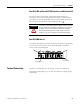
GuardPLC 1600 and GuardPLC 1800 Controllers
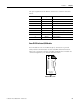
The supply voltage is connected via a 4-pin connector that
accommodates wire sizes up to 2.5 mm
2
(14 AWG). You only need to
connect one wire to L+ and one wire to L-. Both L+ and L- terminals
are internally connected. The other terminal can be used to
daisy-chain 24V DC to additional devices. The power supply
connector is rated to 10 A.
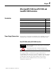
Topic Page
Power Supply Connections 49
Safety-related Digital Inputs 50
Safety-related Digital Outputs 51
Safety-related Analog Inputs 51
High-speed Counters 52
Wire the GuardPLC 1600 Controller 53
Wire the GuardPLC 1800 Controller 54
Wire the GuardPLC 1200 Controller 58
ATTENTION
Before connecting the power supply, check for correct polarity,
value, and ripple.
Do not reverse the L+ and L- terminals or damage to the
controller will result. There is no reverse polarity protection.