
Instruction Manual


Publication 1753-UM001C-EN-P - March 2010 41
Installation Chapter 2
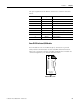
The pin assignment of the Min-D connectors is shown in the table
below.
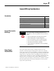
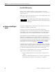
GuardPLC Distributed I/O Modules
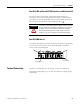
Each module has two 10/100BaseT, RJ-45 connectors to provide
safety-related communication via the GuardPLC Ethernet network.
These two connectors and the GuardPLC distributed I/O module are
connected together by an internal Ethernet switch.
Connection Signal Function
1——
2 RP 5V, decoupled with diodes
3 RxD/TxD-A Receive/Transmit data A
4 CNTR-A Control Signal A
5 DGND Data reference potential
6 VP 5V, positive pole of supply voltage
7——
8 RxD/TxD-B Receive/Transmit data B
9 CNTR-B Control Signal B
L-L- L+ L+
24V DC
RUN
24 V DC
PROG
ERROR
FAULT
FORCE
BL
OSL
GuardPLC Ethernet
10/100 BaseT
1
(—)
2
(—)
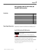
Ethernet Ports 1 and 2