
Instruction Manual

40 Publication 1753-UM001C-EN-P - March 2010
Chapter 2 Installation
See Chapter 16 for information on peer-to-peer communication or
Chapter
18 for information on EtherNet/IP communication.
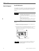
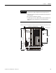
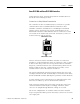
Connections for Non-Safety-Related communication
Three 9-pin Min-D connectors are located on the front of the
controller, providing these communication options.
Designation Function
COMM1 (RS-485) Modbus RTU Slave (1753-L28BBBM or 1753-L32BBBM-8A)
Profibus-DP-Slave 1753-L28BBBP or 1753-L32BBBP-8A)
COMM2 not used
COMM3 GuardPLC ASCII Protocol/HSP
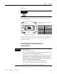
IMPORTANT
The three Min-D connectors are RS-485. You must use an
electrical interface device to connect the controller to an
RS-232 device.
To use COMM3 for HSP, you must use a 1753-CBLDN cable,
which ships with the 1753-DNSI DeviceNet Safety Scanner for
GuardPLC Controllers.
L-L- L+ L+
COMM1
MODBUS
RS-485
24V DC
COMM2COMM3
GuardPLC Ethernet
10/100 BaseT
ASCII/HSP
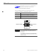
3
(—)
4
(—)
3
(—)
4
(—)
ASCII/HSP Port (COMM 3)
Modbus or Profibus Port
(COMM 1)