
Instruction Manual

324 Publication 1753-UM001C-EN-P - March 2010
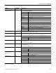
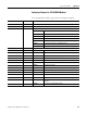
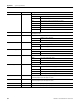
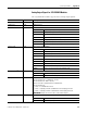
Appendix B System Signal Variables
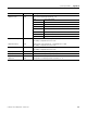
AI[xx].Error Code
(1)
Read Error code of analog input channels
0x01 Error in the analog input module
0x02 Limit value underflow/overflow
0x04 A/D converter faulty; measuring values not valid
0x08 Measured value not within safety accuracy
0x10 Measured value overflow
0x20 Channel not in operation
0x40 Address error of both A/D converters
AI[xx].Value Read Analog value of each channel [INT] from 0…2000 (0V…10V). The validity depends on
the AI[xx].Error Code.
AI[xx].Used Write Configures the channel for operation
0 Channel is not in operation.
1 Channel is operating.
AI[xx].Transmitter Used Write Configures the channel for transmitter supply
0 Transmitter supply is not used.
1 Transmitter supply is used.
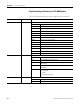
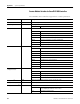
Transmitter Voltage[01] Write Configures switchover of the transmitter supply per group
18.2V
2 26.0V
Transmitter.Error Code Read Error codes of the transmitter unit
0x0001 Error in the transmitter supply
0x0400 FTZ test 1: temperature threshold exceeded
0x0800 FTZ test 2: temperature threshold exceeded
Transmitter[01].Error Code Read Error codes of each transmitter group
0x01 Module error of transmitter supply
0x02 Overcurrent of transmitter supply
0x04 Undervoltage of transmitter supply
0x08 Overvoltage of transmitter supply
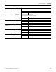
AI[xx].Underflow Read Underflow AI[xx].Value according to AI[xx].Limit LOW.
The validity depends upon the AI[xx].Error Code.
AI[xx].Overflow Read Overflow AI[xx].Value according to AI[xx].Limit HIGH.
The validity depends upon the AI[xx].Error Code.
AI[xx].Limit LOW Write Upper limit of voltage range 0-signal AI[xx].Underflow
AI[xx].Limit HIGH Write Lower limit of voltage range 0-signal AI[xx].Overflow
(1) xx = affected output channel of the controller or module.
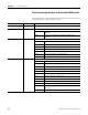
I/O Data Read/Write Description