
Instruction Manual

Publication 1753-UM001C-EN-P - March 2010 321
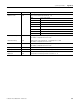
System Signal Variables Appendix B
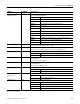
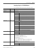
DO[xx].+Error Code
(1)
DO[xx].-Error Code
Read Error code of digital outputs DO+
Error code of digital outputs DO-
0x0001 Error in the digital output module
0x0002 Output switched off due to overload
0x0004 Error reading back the activation of digital outputs
0x0008 Error reading back status of the digital outputs
0x0010 Short-circuit
0x0020 Channel is switched off due to an error in the corresponding DO
channel
0x0040 Zener diode at the output is not alloyed
0x0080 Line break
0x0100 MEZ test of the output switches in the DO+ line caused an error
0x0200 MEZ test of the output switches in the DO- line caused an error
0x0400 MEZ test of the L- test switch caused an error
0x0800 External L+ supply at DO+
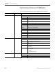
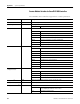
DO.LSLB period
(2)
Write Period during which line monitoring is carried out.
Values in one second increments from 1…100 s.
DO.LSLB time Write Time for Line Short Line Break (LSLB) monitoring.
Values in one millisecond increments from 0 …50 ms. The default is 0 ms.
DO[xx].2-pole Write Configures the module for 2-pole operation
0 1-pole operation
1 2-pole operation
DO[xx].+Value Write Output value for DO channels (DO+)
1-pole (Value:0 or 1)
2-pole, identical to DO- (Value: 0 or 1)
DO[xx].-Value Write Output value for DO channels (DO-)
1-pole (Value:0 or 1)
2-pole, identical to DO+ (Value: 0 or 1
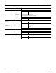
DO[xx].LSLB monitoring Write Configures line control
0 no LSLB (line control)
1 set for LSLB (line control)
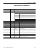
DO[xx]LS monitoring with
reduced voltage
Write Configures line control with reduced voltage
0 normal signal voltage level
1 reduced signal voltage level
DO[xx][xx].in pairs Write Configures line control with channel pairs
Pair 1 channel 1 [01] and channel 2 [02
Pair 2 channel 3 [03] and channel 4 [04
Pair 3 channel 5 [05] and channel 6 [06
Pair 4 channel 7 [07] and channel 8 [08]
(1) xx = affected output channel of the controller or module.
(2) LSLB = Line Short Line Break
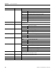
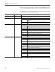
I/O Data Read/Write Description