
Instruction Manual

Publication 1753-UM001C-EN-P - March 2010 317
System Signal Variables Appendix B
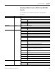
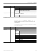
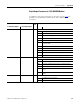
DI.Number of Pulse
Channel
Write Number of pulse outputs (feed outputs)
0 No output channel provided for line monitoring
1 Output channel 1 provided for line monitoring
2 Output channels 1 and 2 provided for line monitoring
3 Output channels 1, 2, and 3 provided for line monitoring
4 Output channels 1…4 provided for line monitoring
5 Output channels 1…5 provided for line monitoring
6 Output channels 1…6 provided for line monitoring
7 Output channels 1…7 provided for line monitoring
8 Output channels 1…8 provided for line monitoring
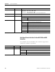
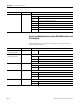
DI Supply[xx]
1753-IB16XOB8 only)
Write Activation of the single DI supply
0 Transmitter supply (1 A) is switched off (default: supply current 40 mA)
1 Transmitter supply (1 A) is switched on
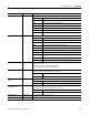
DI.Pulse Slot Write Pulse module slot (LC)
DI.Pulse Channel Write Source channel of pulse feed
0 Input channel
1 Pulse from first DO channel
2 Pulse from second DO channel
3 Pulse from third DO channel
4 Pulse from fourth DO channel
5 Pulse from fifth DO channel
6 Pulse from sixth DO channel
7 Pulse from seventh DO channel
8 Pulse from eighth DO channel
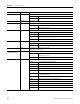
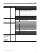
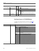
DI.LC Delay
(GuardPLC 1600 and 1800
Controllers and 1753-IB16
and 1753-IB20XOB8
modules)
DI Pulse Delay
(1753-IB8XOB8 and
1753-IB16XOB8)
Write Waiting time for pulse output (short-circuit-proof)
(1) xx = the affected input channel of the controller or module.
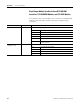
I/O Data Read/Write Description