
Instruction Manual

314 Publication 1753-UM001C-EN-P - March 2010
Appendix B System Signal Variables
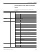
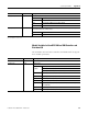
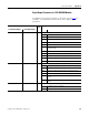
Cnt[0x].GrayCode
(1)
Read/Write Gray code mode of counter 1 or 2
0 Pulse
1Gray
Cnt[0x].Halt
(1)
Read/Write currently not used
Cnt[0x].Reset
(1)
Read/Write Reset for counter 1 or 2
0 Resetting of counter
1 No resetting of counter
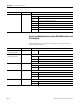
Cnt[0x].State
(1)
Read Error mask of counter 1 or 2
0x01 Error in counter unit
0x02 Error while comparing the counts
0x04 Error while comparing the time stamps
0x08 Error resetting counter
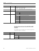
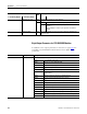
Cnt[0x].Time Overflow
(1)
Read Overflow indicator of time stamp of counter 1 or 2
true 24 bits overflow since last cycle
false No 24 bits overflow since last cycle
Cnt[0x].Time Stamp
(1)
Read Time stamp for Cnt[0x].Value (cyclic 24-bit)
24 bits, time resolution 1µs
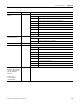
Cnt[0x].Value Overflow
(1)
Read Overflow indicator of counter 1 or 2
true 24 bits overflow since last cycle (only when Automatic Counter
Advance Sense = false)
false No 24 bits overflow since last cycle
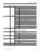
DO.State Read Error mask for all counter outputs
0x0001 Error of the DO section of the module
0x0002 Within the multiple error occurrence time: safety switch 1 faulty
0x0004 Within the multiple error occurrence time: safety switch 2 faulty
0x0008 Within the multiple error occurrence time: test sample tests faulty
0x0010 Within the multiple error occurrence time: readback channels faulty
0x0020 Within the multiple error occurrence time:
active switch-off faulty
0x0100 Within the safety time: CS signals faulty
0x0200 All outputs switched off; total current too high
0x0400 Within the safety time: temperature limit 1 exceeded
0x0800 Within the safety time: temperature limit 2 exceeded
0x01000 Within the safety time: auxiliary voltage monitoring: undervoltage
0x02000 Within the multiple error occurrence time: status of the safety switches
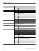
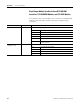
I/O Data Read/Write Description