
Instruction Manual

Publication 1753-UM001C-EN-P - March 2010 313
System Signal Variables Appendix B
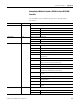
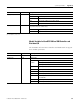
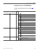
Board.State Read Error mask for the module
0x000 I/O processing may be running with errors
0x001 No I/O processing (CPU not in RUN)
0x002 No I/O processing during start-up tests
0x004 Manufacturing interface running
0x010 No I/O processing due to faulty parameterization
0x020 No I/O processing due to exceeded fault rate
0x040 No I/O processing because configured module is not plugged in
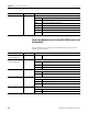
Cnt.State Read Error mask of both counters
0x0000 No errors detected
0x0001 Error of the counter section of the module
0x0002 Error while comparing the time base
0x0004 Addressing error while reading the time base
0x0008 Parameterization of the time base corrupted
0x0010 Addressing error while reading the counts
0x0020 Parameterization of counter corrupted
0x0040 Addressing error while reading the Gray codes
0x0080 Within the multiple error occurrence time: test sample test faulty
0x0100 Error of the module
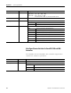
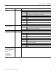
Cnt[0x].Value
(1)
Read Counts of counter 1 or 2 (cyclic 24-bit)
24 bits for pulse counter
4 bits for Gray code for GuardPLC 2000 controllers;
3 bits for Gray code for GuardPLC 1200 controllers
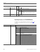
Cnt[0x].5/24V Mode
(1)
Read/Write 5V or 24V mode of counter 1 or 2
The write values must have initial values or constants.
05V
1 24V
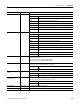
Cnt[0x].Auto Advance
Sense
(1)
Read/Write Automatic recognition of direction of counting for counter 1 or 2
0 Manual setting of direction of counting
1 Automatic recognition of direction of counting
Cnt[0x].Direction
(1)
Read/Write Direction of counting for counter 1 or 2
(only when Automatic Counter Advance Sense = false)
0Up
1Down
Cnt[0x].Dummy1 Read/Write reserved memory space for future use
Cnt[0x].Dummy2 Read/Write reserved memory space for future use
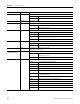
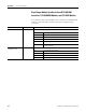
I/O Data Read/Write Description