
Instruction Manual

Publication 1753-UM001C-EN-P - March 2010 305
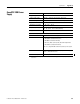
Appendix
B
System Signal Variables
Introduction
Programming Controller
Data
The controller supports system variables that you can configure.
The system variables are defined as:
• SAFE: the controller can use this information in safety-related
functions.
• NON-SAFE: additional information that safety functions must not
rely on.
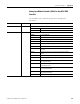
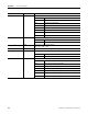
These are the system variables.
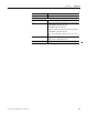
Topic Page
Programming Controller Data 305
I/O Variables 307
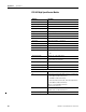
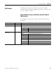
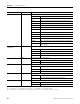
System Variable Unit/Value Read/Write Description
(1)
Contact Assembly 1
Contact Assembly 2
Contact Assembly 3
Contact Assembly 4
true
false
Write On true, the contact closes; on false the contact does not close.
Only available for a GuardPLC 2000 controller.
[BOOL]
NON-SAFE
Cooling Fan State 0, 1, 2 Read 0 = normal
1 = fans OK
2 = fan error
Only available for a GuardPLC 2000 controller.
[BYTE]
NON-SAFE
Cycle Time milliseconds Read Duration of the last cycle
[UDINT]
SAFE
Date Time Seconds
Date Time
Milliseconds
seconds
milliseconds
Read Time passed since 1970. An automatic switchover from summer to winter time is
not supported.
[UDINT]
NON-SAFE
Emergency Stop 1
Emergency Stop 2
Emergency Stop 3
Emergency Stop 4
true
false
Write True triggers Emergency Off
[BOOL]
SAFE
Use these signals to force all inputs and outputs to the zero/OFF state from within
the user program.