
Instruction Manual

Publication 1753-UM001C-EN-P - March 2010 283
Appendix
A
Specifications
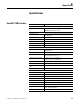
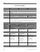
GuardPLC 1200 Controller
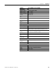
Attribute 1754-L28BBB
Controller
User Memory 500 KB application code memory
500 KB application data memory
Digital Inputs
Number of inputs 20 (not electrically isolated from each other, isolated from
the backplane)
Nominal input voltage 24V DC
On-state voltage 10V DC…30V DC
On-state current 2 mA @ 10V DC, 13 mA @ 30V DC
Off-state voltage, max 5V DC (max)
Off-state current, max 1.5 mA max (1 mA @ 5V)
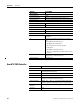
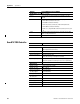
Digital Outputs
Number of outputs 8 (not electrically isolated from each other, isolated from
the backplane)
Output voltage range 18.4V…26.8V
Output current 0.5 A per channel (channel 1…6)
2 A per channel (channel 7, 8)
Surge current per channel 1 A for 10 ms @ 1 Hz (channel 1…6)
4 A for 10 ms @ 1 Hz (channel 7, 8)
Minimum current load 2.5 mA per channel
On-state voltage drop, max 2.0V DC @ 500 mA
Off-state leakage current,
max
1 mA per channel
Temporary overload Output switches off until overload is eliminated
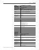
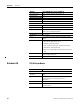
Counters
Number of counters 2
Inputs per counter 3 (Input A, Input B, Z/Gate/Reset)
Counter resolution 24 bit
Input frequency, max 100 kHz in counter modes (input A)
Trigger Negative edge
Edge steepness 1 V/μs
Duty cycle 50% @ 100 kHz
Input voltages 4.5V…5.5V for 5V input
13V…26.4V for 24V input
Input current Typ. 15 mA, ≤ 3 mA