
Instruction Manual


266 Publication 1753-UM001C-EN-P - March 2010
Chapter 21 Communicate with ASCII Devices
D-shell connector. This mini-DIN connector is not commercially
available, so you cannot make this cable.
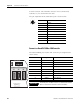
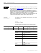
The pin assignment of the ASCII Serial port is shown below.
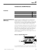
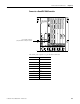
Connect to a GuardPLC 1600 or 1800 Controller
The ASCII COMM3 port location and connector pin assignment are
shown below.
Connection Signal Function
1 --- ---
2 RP 5V, decoupled with diodes
3 RxD/TxD-A Receive/Transmit data A
4 CNTR-A Control Signal A
5 DGND Data reference potential
6 VP 5V, positive pole of supply voltage
7 --- ---
8 RxD/TxD-B Receive/Transmit data B
9 CNTR-B Control Signal B
IMPORTANT
The ASCII port is RS-485. You must use an electrical interface
device to connect the controller to an RS-232 device.
4
5
7
1
2
8
6
3
Pin Function
1 24V DC
2 ground (GND)
3 request to send (RTS)
4 received data (RxD)
5 received line signal detector (DCD)
6 clear to send (CTS)
7 transmitted data (TxD)
8 ground (GND)
9 not applicable
L- L+ L+
COMM3
ASCII
RS-485
24V DC
COMM2 COMM1
GuardPLC Ethernet
10/100 BaseT
PROFIBUS
3
(—)
4
(—)
3
(—)
4
(—)