
Instruction Manual


Publication 1753-UM001C-EN-P - March 2010 25
Overview of Safety Controllers Chapter 1
1753 Relay Output and Analog I/O Modules
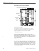
GuardPLC 2000 System
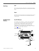
The GuardPLC 2000 controller is a modular system consisting of a
controller (1755-L1), which provides central CPU and communication
functions, and a separate power supply and I/O residing in a
GuardPLC 1755-A6 chassis. A maximum of six I/O modules may be
used in a single system.
The GuardPLC 2000 controller has one active RS-232 serial port for
non-safety related communication. It also features an Ethernet port for
configuration and safety-related communication. The lower DB9 port
supports RS-232 ASCII (read-only) communication; the upper port is
inactive.
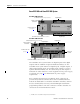
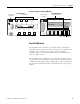
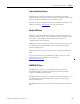
1753-OW8
8 Digital Outputs
DO 1
1 2
DO5 DO6 DO7 DO8
DO 2
3 4
DO 3
5 6
DO 4
7 8
9 10 11 12 13 14 15 16
L-L- L+ L+
24V DC
L-L- L+ L+
AI
T1 I1 L- T2 I2 L-
AI
T3 I3 L- T4 I4 L-
AI
T5 I5 L- T6 I6 L-
AI
T7 I7 L- T8 I8 L-
1 2 3 4 5 6 7 8 9 101112 131415161718 192021222324
24V DC
RUN
24 V DC
GuardPLC Ethernet
10/100 BaseT
PROG
ERROR
FAULT
FORCE
BL
OSL
1
<—>
2
<—>
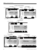
1753-IF8XOF4
8 Analog Inputs
4 Analog Outputs
O1 O2 O3 O4
AO
STD ANALOG OUTPUTS
+-+-+-+-
25 26 27 28 29 30 31 32
1753-OW8 Module
Ethernet Ports (on Bottom of Module)
Voltage Supply
Connection
Relay Outputs
Relay Outputs
Voltage Supply
Connection
Ethernet Ports (on Bottom of Module)
Standard Analog Outputs
Safety Analog Inputs
1753-IF8XOF4 Module