
Instruction Manual

249Publication 1753-UM001C-EN-P - March 2010 249
Chapter
20
Use the GuardPLC Controller as a Scanner
Introduction
Prepare the GuardPLC
Controller for Class 1
Scanner Connections
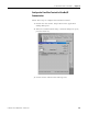
Make sure the GuardPLC controller resource has the EtherNet/IP
protocol added under the Protocols folder in the RSLogix Guard PLUS!
Hardware Management project tree. If it does not, see page 203
for
instructions on adding EtherNet/IP protocol to the project.
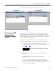
The GuardPLC controller’s scanner I/O assembly consists of two
buffers: one to store input data and the other to store output data.
When a new connection is opened from the GuardPLC controller to
an I/O module, the scanner input buffer receives data from the I/O
module and the scanner output buffer stores data that is sent to the
I/O module.
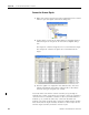
You must allocate enough space in both of these buffers to store the
corresponding data. You do this by creating signals in the Signal
Editor and assigning them to the scanner assembly. For detailed
information on defining signals by using the Signal Editor, refer to the
Using RSLogix Guard PLUS! Software with GuardPLC Controllers
Programming Manual, publication 1753-PM001
.
Topic Page
Prepare the GuardPLC Controller for Class 1 Scanner Connections 249
Configure the EtherNet/IP Driver 252
Configure Connections in RSNetWorx for EtherNet/IP Software 254
Open a Connection to a Logix Controller 260
Save the Connection Configuration in the GuardPLC Controller 262
Remove the Connection Configuration 263